powered by CADENAS

Manual

Manual

2.6.1.  Insert 2D from the Standard and supplier parts library

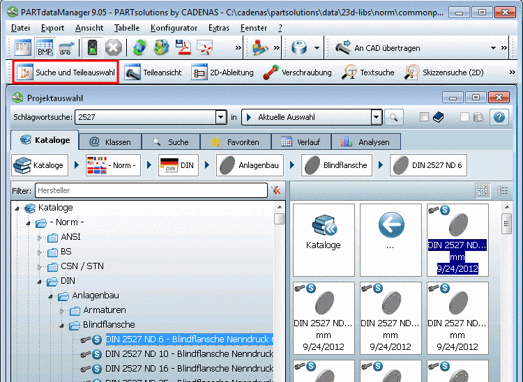
The following describes how you can insert 2D single parts from the Standard and supplier parts library into your CAD system.

  1. In the PARTsolutions menu, click on Insert 2D.

    -> The display changes to the PARTdataManager.

PARTsolutions
Insert 2D
Seamless
Replace
Extras
Execute Geometric Search
Insert Connection
User library
Settings
Info

  1. In the Part selection choose the desired part.[4]

    PARTdataManager - Part selection

    PARTdataManager - Part selection

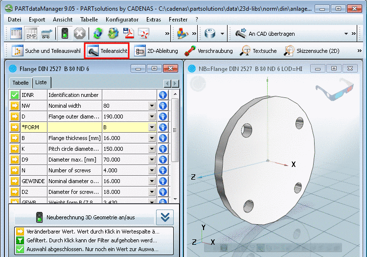
  2. In the Part view determine the desired characteristics.

    PARTdataManager - Part view

    PARTdataManager - Part view

  3. Creating a 2D derivation

    To do so, you have the following options:

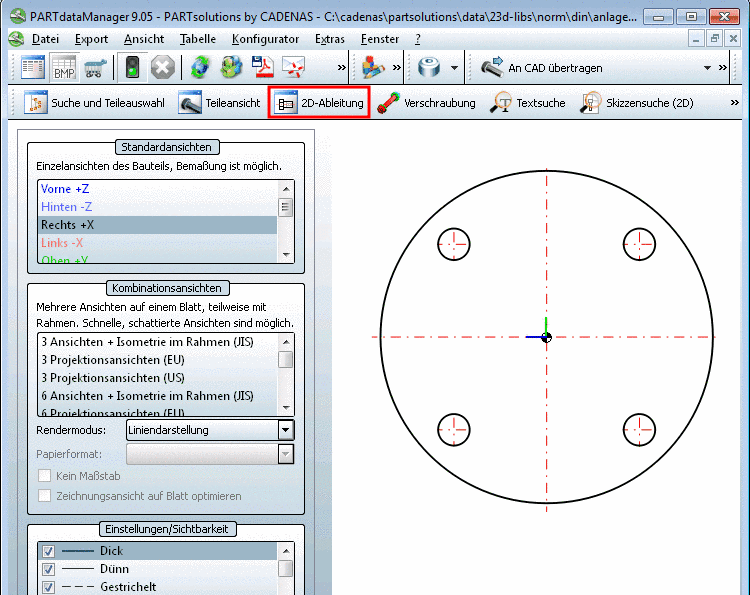
    1. Click on the button 2D derivation .

      -> The 2D view window opens.

      PARTdataManager - 2D view

      PARTdataManager - 2D view

      Select a view.[5]

    2. Alternatively you can also skip the opening of the 2D view and click on Transfer to CAD directly.

      The Choose view to pass.... window opens.

      Select the desired view.

      Choose view to pass...

      Choose view to pass...

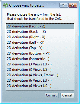
      The following views are available in the Choose view to pass... window:

      • 2D derivation (front - Z)

      • 2D derivation (back - - Z)

      • 2D derivation (right - X)

      • 2D derivation (left - - X)

      • 2D derivation (top - Y)

      • 2D derivation (bottom - - Y)

      • 2D derivation (isometric-)

      • 2D derivation (3 views EU-)

      • 2D derivation (3 views US-)

      • 2D derivation (4 views, frames-)

      • 2D derivation (6 views EU-)

      • 2D derivation (6 views US-)

      • 2D derivation (frame ANSI -)

      • 2D derivation (frame ANSI A - A)

      • 2D derivation (frame ANSI B - B)

      • 2D derivation (frame ANSI C - C)

      • 2D derivation (frame ANSI D - D)

      • 2D derivation (frame ANSI E - E)

      • 2D derivation (frame ANSI (BOM)-)

      • 2D derivation (frame ANSI A (BOM) - A)

      • 2D derivation (frame ANSI B (BOM) - B)

      • 2D derivation (frame ANSI C (BOM) - C)

      • 2D derivation (frame ANSI D (BOM) - D)

      • 2D derivation (frame ANSI E (BOM) - E)

      • 2D derivation (frame DIN -)

      • 2D derivation (frame DIN A0 - A0)

      • 2D derivation (frame DIN A1 - A1)

      • 2D derivation (frame DIN A2 - A2)

      • 2D derivation (frame DIN A3 - A3)

      • 2D derivation (frame DIN A4 - A4)

      • 2D derivation (frame DIN (BOM) - )

      • 2D derivation (frame DIN A0 (BOM) - A0)

      • 2D derivation (frame DIN A1 (BOM) - A1)

      • 2D derivation (frame DIN A2 (BOM) - A2)

      • 2D derivation (frame DIN A3 (BOM) - A3)

      • 2D derivation (frame DIN A4 (BOM) - A4)

  4. Click on the button (option a) or confirm with Commit (option b)[6]-> The view changes back to the CAD system.

  5. Insert the part and/or assembly with the placement method of your CAD system.


[4] A more detailed description of PARTdataManager can be found under Section 3.1, “ PARTdataManager ”.

[5] More detailed information about the 2D view can be found under Section 3.1.1, “Basic functions ”.

[6] You can also export the part via "Export in file". More detailed information under Section 3.1.2.1.2, “ Export to CAD systems without PARTsolutions interface - Export in file ”.