Manual
Login
Our 3D CAD supplier models have been moved to 3Dfindit.com, the new visual search engine for 3D CAD, CAE & BIM models.
You can log in there with your existing account of this site.
The content remains free of charge.

Top Links
Manual
 |
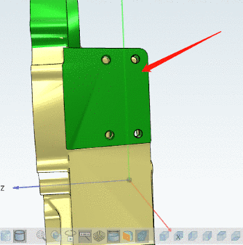
In order for conversion from Creo to STEP format (e.g. in PLM Synchro) to work properly, some things have to be payed attention to.
With wrong settings holes, for example, are not correctly converted and then are not selectable (e.g. in Partial search).

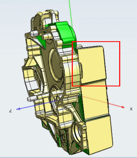
If all settings are made as described in following notes, the individual features will be correctly converted.
-
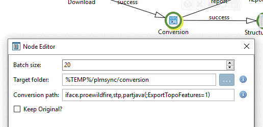
For versions < V11 SP8 the Conversion path has to be adjusted:
iface.proewildfire,stp,partjava(;ExportTopoFeatures=1)
V11SP4, for example still has a wrong Conversion path:
iface.proewildfire,stp,partjava
-
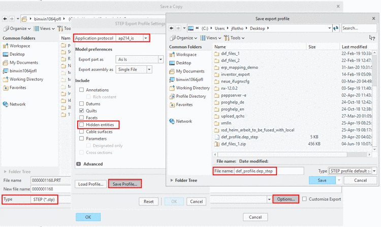
The STEP Export Profile Settings have to be correctly set in Creo and the export profile has to be correctly entered in the
config.profile.-
Call the dialog
STEP Export Profile
          Settings
via "File > Save As (Type=STEP) > . Under Application protocol, choose the option "ap214_is" and deactivate the option Hidden entities.
Save the file
def_profile.dep_stepto any location by clicking on (e.g. under C:\Test).-
Add the following line with the appropriate path statement in the
config.profile.export_profiles_step C:\Test\def_profile
In the case of PLM Synchro, for example, the run can now be performed.
-
![[Note]](/community/externals/manuals/%24%7Bb2b:MANUALPATH/images/note.png)
