Manual
Login
Our 3D CAD supplier models have been moved to 3Dfindit.com, the new visual search engine for 3D CAD, CAE & BIM models.
You can log in there with your existing account of this site.
The content remains free of charge.

Top Links
Manual
 |
A 3-D solid must always be created on a 2-D sketch. This 2-D sketch is created in its own menu area, the Sketcher.
The following describes the procedure step by step based on an example of a simple cylinder.
-
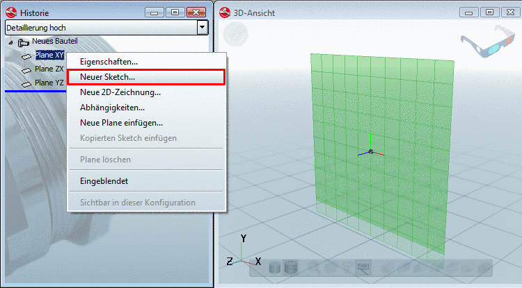
In the History menu area, you can find three basic planes for the construction sketches.
With your right mouse button click on one of these planes (in this case XY) and select the menu point New sketch... in the context menu.
-
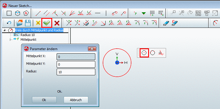
In order to create a cylinder you must first draw the basic plane, a circle.
Click on the button Circle with center point and radius/point.
Set a center point by moving the cursor to the KO origin and simply "drop" it with a mouse-click.
When you move your cursor away from the center point, you "pull" the circle "open" and increase its radius. Fix the size with a simple mouse-click as well.
-
Click on the Sketch OK
 button, in order to confirm your entries.
-> The 2-D Sketcher is closed.
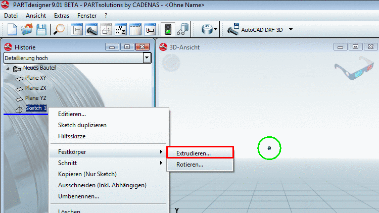
-> In the History area the construction step Sketch 1 shows up.
-
With your right mouse button, click on Skizze1 and select the command Base, Extrude....
-
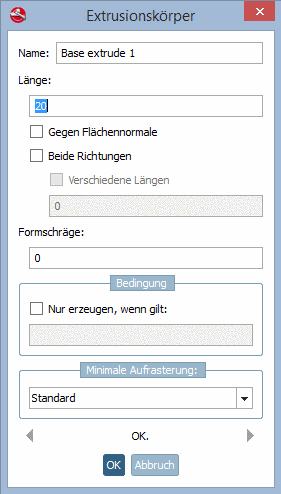
-> The Extrusion solid window opens.
Set the length (here 20 mm) of the circumference and confirm with .[a]
[a] If, in case you want to define the length through a variable value, apply a respective variable "L" in the menu area Variables . Read the following for more information: Section 7.5.3, “ Variables ”.
-
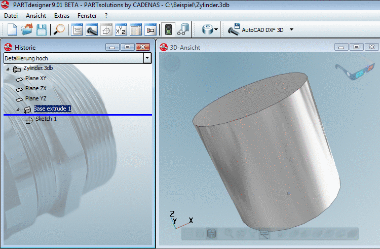
In the History menu area, in connection with Sketch 1, the construction step Base extrude 1 shows up.
-> In the 3D view the circle is extruded with a value of 20mm to the cylinder.
-
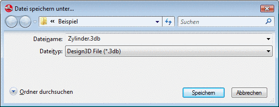
Set the name and storage location of the geometry and confirm with .


![[Note]](/community/externals/manuals/%24%7Bb2b:MANUALPATH/images/note.png) |
Note |
|---|---|
A more detailed example can be found under Chapter 3, Training Documentation. | |
