Manual
Login
Our 3D CAD supplier models have been moved to 3Dfindit.com, the new visual search engine for 3D CAD, CAE & BIM models.
You can log in there with your existing account of this site.
The content remains free of charge.

Top Links
Manual
 |
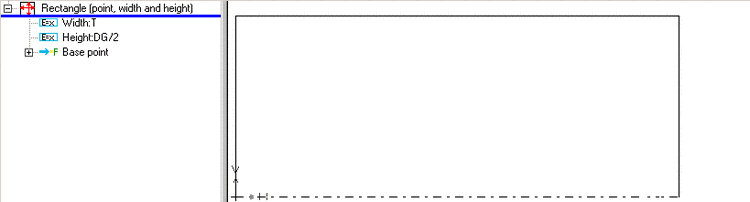
Create a new sketch to create the inner thread.
-
-
![[Note]](/community/externals/manuals/%24%7Bb2b:MANUALPATH/images/note.png)
Note Not until a Rotation axis has been defined, are the Cylindrical thread by length and Conical thread by lengths buttons defined!
-
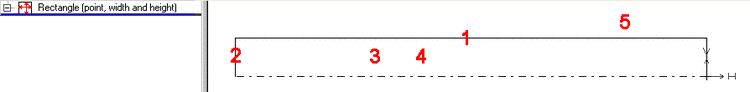
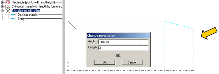
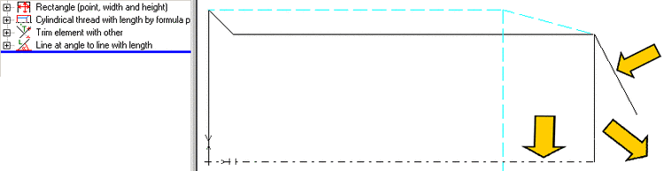
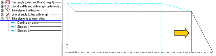
Click on the respective sketch elements and areas and follow the notes in the footer:
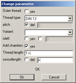
The Change parameter window opens.
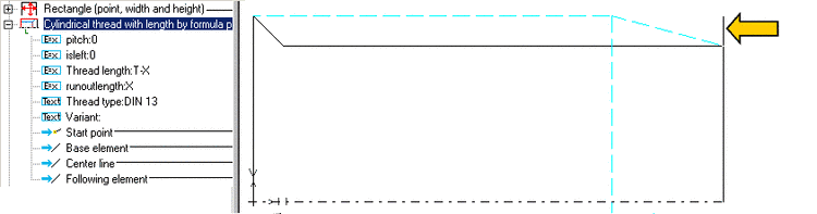
Insert 'T-X' for the Thread length and 'X' for the Run out length.
-
-
-
-
-
-
-
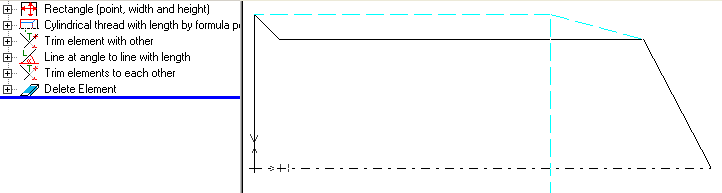
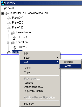
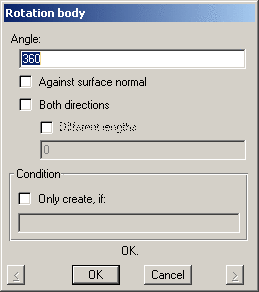
Select Cut -> Rotate... in the context menu of sketch 3 and confirm with OK in the Rotational solid window.
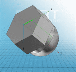
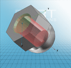
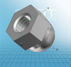
--> In the 3D view menu area the finished cap nut is displayed.
-
Insert the Filenames and/or the storage location and save the file. --> The Part information menu[6]will open.
If needed, change the available entries and confirm with OK. --> Thus the cup nut geometry is finished.
Note In order to show the Geometryin the Preview, first you have to click another feature in the Project selection menu, and then again the cap_nut.3db-file .
Note Further information on the creation of an outer thread with different variants of thread pitch is found under Section 7.5.4.3.11, “ Threads ” .