Manual
Login
Our 3D CAD supplier models have been moved to 3Dfindit.com, the new visual search engine for 3D CAD, CAE & BIM models.
You can log in there with your existing account of this site.
The content remains free of charge.

Top Links
Manual
 |
Catalog parts that are going to be used in architectural CAD systems require specific classifications. Via classifications meta-information as well as “relationship-knowledge” will be hosted and transferred to the target systems. Following BIM / AEC classifications do exist today:
![[Note]](/community/externals/manuals/%24%7Bb2b:MANUALPATH/images/note.png)
In the following, an example part will be equipped with the Revit-Family-Templates Classification:
-
Make sure, that the REVIT class system is installed.
If not, first use PARTupdate to get it or write an e-mail to catalogs@cadenas.de.
Start PARTproject and navigate to the part where the classification should be applied
Click on the dots at the end of the line Classification (REVIT).
-
Confirm the window with OK and switch to the 3DB file in PARTproject
Confirm with and click on the dots at the end of the line "Attributes (REVIT)".
-
Depending on the selected class there are different attributes to be filled out now (e.g. for a door the negative solid for the cut-out in the wall must be specified). Please fill out all this fields or map them to the corresponding table variable.
Confirm the window with and switch to the corresponding 3DB file in the PARTproject folder/file structure
-
Open the 3DB and place the required Revit Family Template mapping Insertion point. The name can freely be chosen, but take care on position and direction.
An instructing overview on positioning depending on product category can be found under ... <cuboids + examples in progress> .
For assemblies, please always chose the 3DB, that contains the placement point.
The placement point should be in a fixed / static position related to possible variants.
-
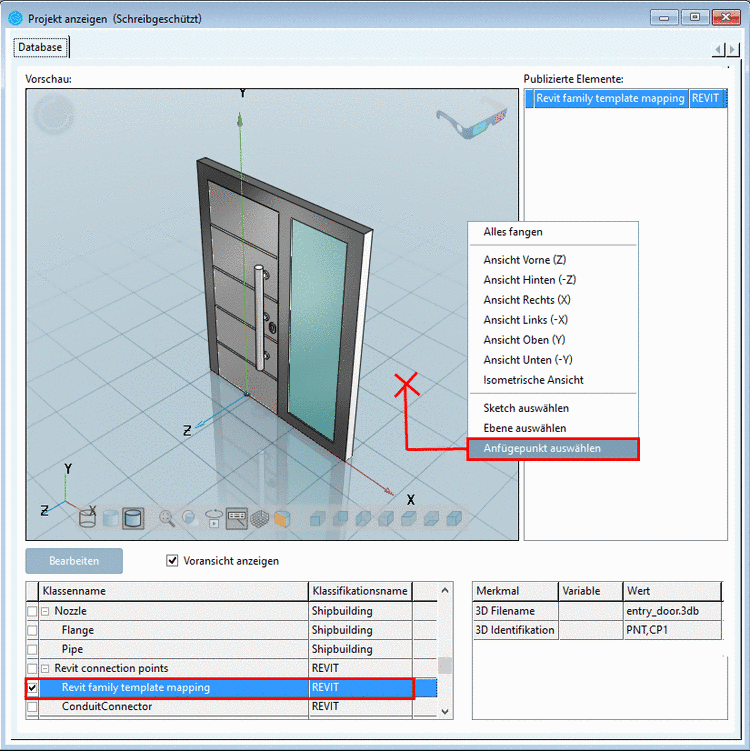
Right-click in the PARTproject 3D preview window and select the command Choose connection point. Then please select the entry Revit family template mapping:
-
Please click again on the PRJ file in the PARTproject folder structure and then check if all entries are set up correctly now in the two classification lines.
The classification is now complete. It is recommended, that an REVIT export check is performed additionally in order to check the correct placement and handling of the negative solid.


![[Tip]](/community/externals/manuals/%24%7Bb2b:MANUALPATH/images/tip.png)