Manual
Login
Our 3D CAD supplier models have been moved to 3Dfindit.com, the new visual search engine for 3D CAD, CAE & BIM models.
You can log in there with your existing account of this site.
The content remains free of charge.

Top Links
Manual
 |
Dimensionings and annotations can be set in the project parametrically, thus are available in PARTdataManager for the 2D derivation and are transferred to the CAD system during the export.
| Horizontal, vertical and parallel dimensioning | Radial dimensioning | Angular dimensioning | Annotations / Position numbers for list of material |
|
|
|
|
|


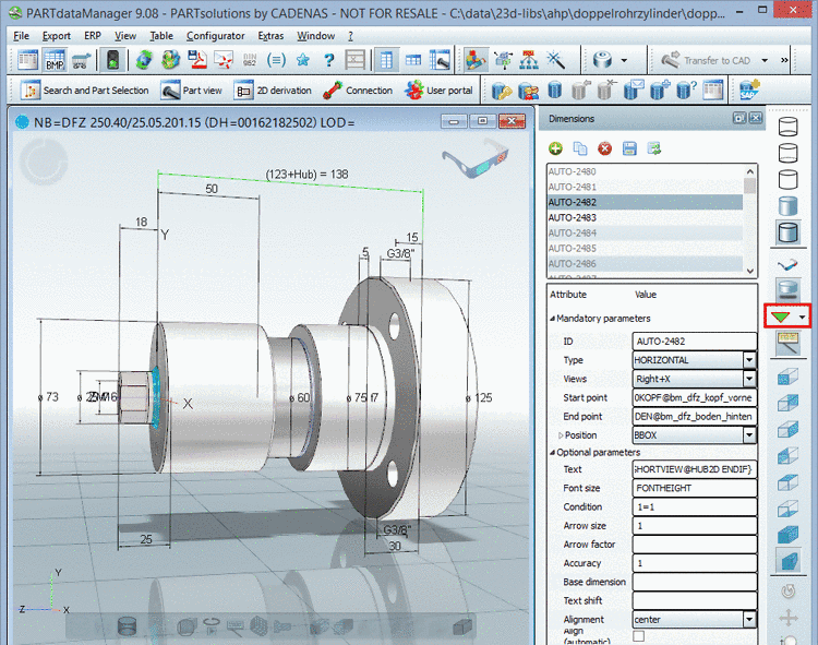
The dimensionings are created and displayed directly in the 3D view of PARTdataManager.
-
The user interface is a docking window. The docking window itself consists of two dialog areas:
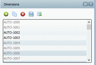
In the upper dialog area the IDs of all dimensionings of the loaded part are listed (AUTO-1000, AUTO-1001, AUTO-1002 etc.).
When clicking on an ID the respective view is loaded in the 3D view and the dimensioning is marked in green. Conversely, when clicking on a dimensioning in the 3D view the respective line is marked in the list of IDs on the right side.
As soon as all Mandatory parameters are set, the dimensioning is displayed in the 3D view.
-
When a certain dimensioning is selected, then in the lower dialog area, all parameters of this dimensioning are listed, namely separated in Mandatory parameters and Optional parameters. Here, parameters can be set or changed. Changes become visible in the 3D view at once (if the mandatory parameters are set).
You can find detailed information on the mandatory parameters in the single chapters of the dimensioning types. Detailed information on the optional parameters can be found in an own chapter Section 8.4.1.7, “ Optional parameters ”.
-
Changes of values are signalized by an Undo icon
 , once in the list of dimensionings in the upper
dialog area and once at the single parameters. So you can either undo
all parameters of a dimensioning or single ones.
, once in the list of dimensionings in the upper
dialog area and once at the single parameters. So you can either undo
all parameters of a dimensioning or single ones.The Undo icon is displayed as long as you did not click on the button Save changes
 . In this case there is no Undo possible
anymore.
. In this case there is no Undo possible
anymore. -
On the left side of the ID list you have the following buttons available:
-
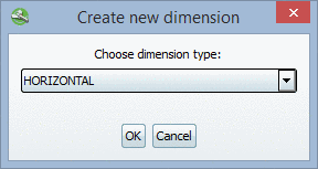
When clicking on the button Create new dimension
 the dialog box Create new dimension opens.
In the list field, under Choose dimension type select the desired option:
After confirmation by clicking on the dialog area with the respective parameters is opened.
-
–> A copy of the dimensioning selected in the list is created.
-
–> Changes are saved in the file
customdimensions.txt.As long as you do not click on the button Save changes
, at the ID line above and at each changed
parameter an icon is displayed. Clicking on the icon you can
undo the respective action. -
–> The selected dimensioning is removed from the list; however, it can be refreshed again via button Refresh contents
 . Not before the button Save changes is clicked, deleting is completed and there
is no "Undo" possible anymore.
. Not before the button Save changes is clicked, deleting is completed and there
is no "Undo" possible anymore. -
–> If changes have been made directly in the file
customdimensions.txt, the user interface should be refreshed.
-
-
-
Possibly at first set the needed insertion points
Since the measuring points reference to connection points, they must either already be available within the part or specifically set.
-
Create file to save the dimensioning parameters
Create a file
customdimensions.txt. -
Reference file for dimensioning parameters
In the assembly configuration project file (*asmcfg.prj) and in the assembly template project file (*asmsbl.prj) create the key CUSTOMDIMENSIONS.
Key value is the name of the created file, where the dimensioning parameters are saved.
CUSTOMDIMENSIONS=customdimensions.txt
-


![[Note]](/community/externals/manuals/%24%7Bb2b:MANUALPATH/images/note.png)
