Manual
Login
Our 3D CAD supplier models have been moved to 3Dfindit.com, the new visual search engine for 3D CAD, CAE & BIM models.
You can log in there with your existing account of this site.
The content remains free of charge.

Top Links
Manual
 |
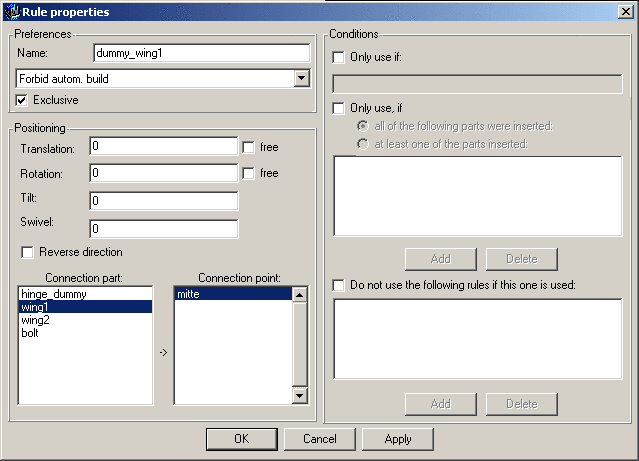
Now the rules will be defined which result in the correct creation of an assembly.
On the
connection point ( ) of the dummy part
(base_dummy) the Connection part "wing1" is connected via a Rule to the Connection point "middle".
) of the dummy part
(base_dummy) the Connection part "wing1" is connected via a Rule to the Connection point "middle".
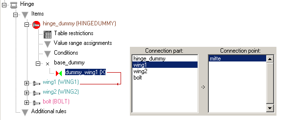
"wing1" is the first "real" part in the assembly.
Via further rules you now connect wing1 with wing2 and bolts or alternatively wing2 with bolts.
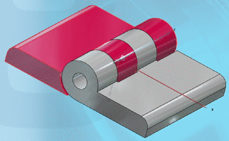
After all connections have been completed, the following image shows up: (Assembly via option list and table row selection has been complete)

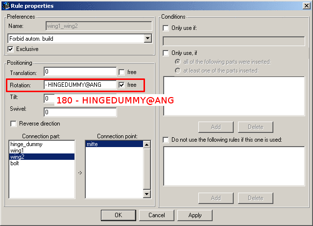
In order to be able to variably control the angularity, do the following:
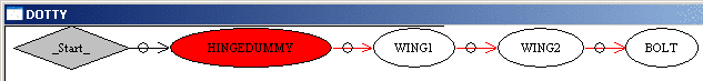
If you open the assembly configuration in the PARTdataManager, after selecting the button assembly structure table , a graphic shows you how the single parts are connected via the rules.

![[Note]](/community/externals/manuals/%24%7Bb2b:MANUALPATH/images/note.png)
