Manual
Login
Our 3D CAD supplier models have been moved to 3Dfindit.com, the new visual search engine for 3D CAD, CAE & BIM models.
You can log in there with your existing account of this site.
The content remains free of charge.

Top Links
Manual
 |
There is a possibility to automatically import DWG/DXF files as 3d geometry. This is interesting for profile manufactures, who only have 2D files but would like to use GeoSearch or provide an eCATALOGsolutions catalog. The function only makes sense for parts which are semi-finished products and are sold by the metre.
The chargeable
license CNS2009*PSADDONS*EXTRUSIONNODE is
required:
-
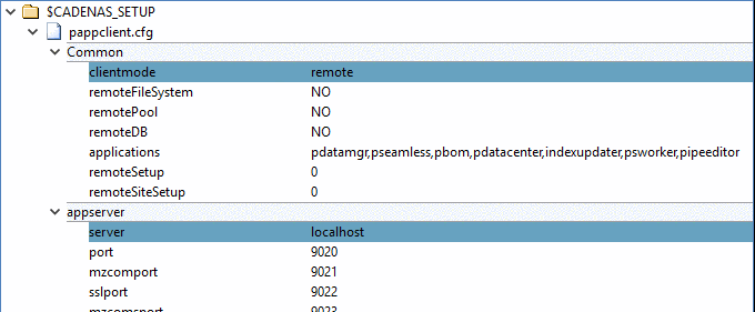
In the configuration file
pappclient.cfg, under blockCommonset the keyclientmodeto the valueremoteand under blockappserverthe keyservertolocalhost. -
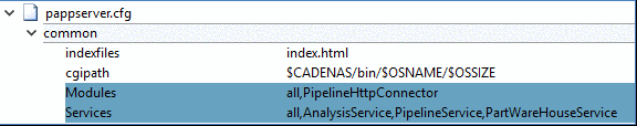
In the configuration file
pappserver.cfg, under BlockCommon, set the keyModulesto the valueall,PipelineHttpConnectorand the keyServicesto the valueall,AnalysisService,PartWareHouseService,PipelineService. -
Start PARTapplicationServer with command:
C:\CADENAS\SOFTWARE\bin\x86\64\pappserver.exe –e
-
Create a PLMsynchro pipeline using PLMsynchro Wizard.
See Section 1.2.2.1, “ Basic setup via wizard”.
The setting under Conversion doesn't matter, because this node will be replaced.
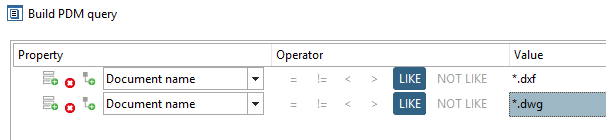
Under Query use following setting, for example:
Now the pipeline created by Wizard looks like this:
-
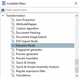
Delete the node Conversion and replace it by the node Extrusion. You can find the node Extrusion in the docking window Available filters. Simply draw it into the dialog area of pipeline and create respective edges anew. Possibly add the Report node in addition.
-
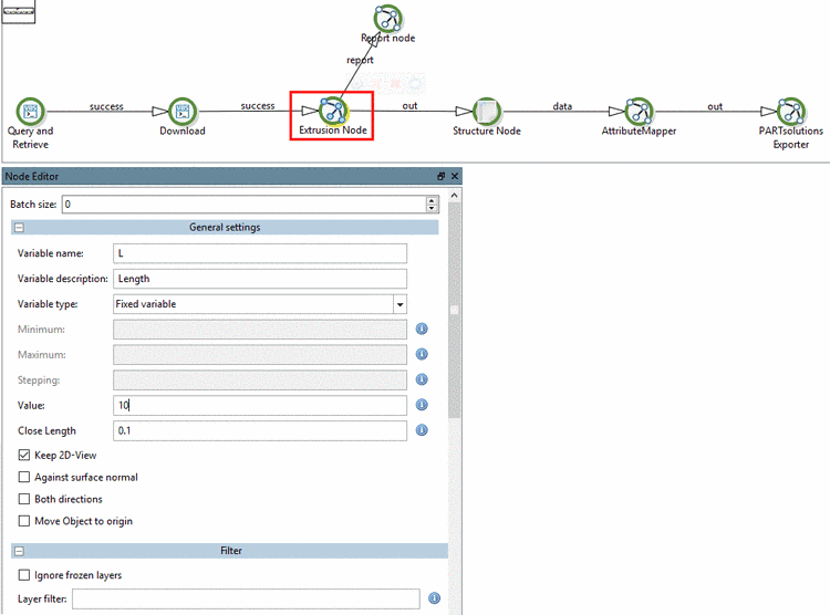
Perform the settings for the Extrusion node:
Batch size: This setting is not relevant for extrusion per se. The Extrusion node can be executed as "distributed node"; that's why this option is shown. Batch size states how many tasks are allocated per client. In standard case leave 0. This means that no fixed value is set.
-
Variable name: Name of variable, which controls the length of semi-manufactured product.
Variable description: Variable description which is displayed in PARTdataManager below the variable.
Minimum (only active when selecting Value range): Minimum value of value range variable
Maximum (only active when selecting Value range): Maximum value of value range variable
Stepping (only active when selecting Value range): optionally
Value (only active when selecting Fixed variable): Variable value for the length of manufactured product
-
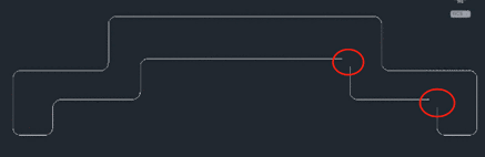
Close Length (default 5): Up to this distance two points will be connected automatically in order to achieve a closed sketch.
Against surface normal: The extrusion is performed in opposite direction.
Both directions: The extrusion is performed in both directions.
Move Object to origin: The lower left corner of the created 3D object is moved in direction of coordinate origin, in order for the object not to be placed "anywhere". Depending on drawing it could be that the object is a little bit moved from the origin.
Presently unit cannot be set. If possible, the unit for the created 3db is taken from the drawing. Otherwise per default mm is supposed as unit.
-
Ignore frozen layers: If this option is activated, all frozen layers are ignored during import.
-
Layer filter: Enter those layer names here, which shall be ignored during import. Wildcard * can be used at the beginning or at the end of a layer name or both at beginning and end.
-
Perform the settings for the PARTsolutions Exporter node:
In this example Supplier Parts is set as catalog type.
-
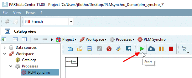
Now click on the Start button
 to execute the PLM Synchro process.
 -
Check the process in Dashboard.
-
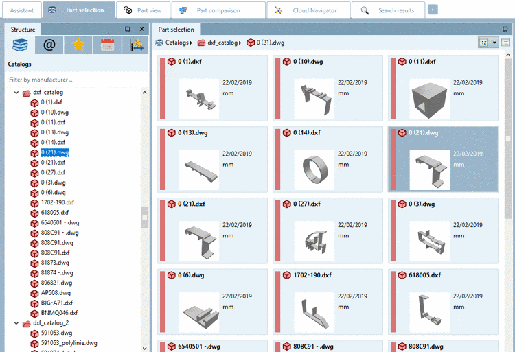
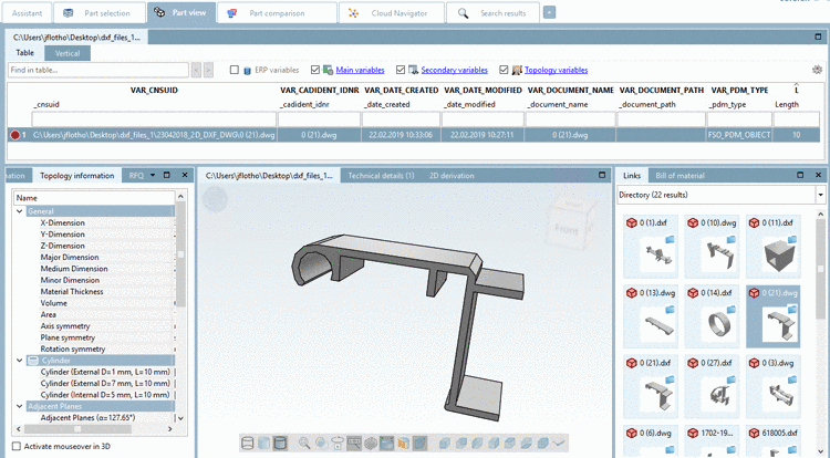
Open PARTdataManager to view the result.

![[Note]](/community/externals/manuals/%24%7Bb2b:MANUALPATH/images/note.png)