Manual
Login
Our 3D CAD supplier models have been moved to 3Dfindit.com, the new visual search engine for 3D CAD, CAE & BIM models.
You can log in there with your existing account of this site.
The content remains free of charge.

Top Links
Manual
 |
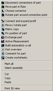
 Disconnect connection of
part. More information under Section 5.3.7, “
Disconnect connection of part”.
Disconnect connection of
part. More information under Section 5.3.7, “
Disconnect connection of part”. Move part to nut. More
information under Section 5.3.3, “Move part
in flute
”.
Move part to nut. More
information under Section 5.3.3, “Move part
in flute
”. Choose connector. More
information under Section 5.3.4, “
Choose connector”.
Choose connector. More
information under Section 5.3.4, “
Choose connector”.-
 Rotate part at connection
point. More information under Section 5.4.2, “
Rotate part around connection point
”.
Rotate part at connection
point. More information under Section 5.4.2, “
Rotate part around connection point
”.  Connect and lengthen
profile. More information under Section 5.4.3, “
Combine and expand profile
”.
Connect and lengthen
profile. More information under Section 5.4.3, “
Combine and expand profile
”. Move/rotate part. More
information under Section 5.4.4, “
Move / rotate part”.
Move/rotate part. More
information under Section 5.4.4, “
Move / rotate part”. Matrix copy. More
information under Section 5.4.5, “
Matrix copy
”.
Matrix copy. More
information under Section 5.4.5, “
Matrix copy
”. Fix part to position.
More information under Section 5.4.6, “
Fix part to position
”.
Fix part to position.
More information under Section 5.4.6, “
Fix part to position
”. Exchange part. More
information under Section 5.4.8, “
Replace part”.
Exchange part. More
information under Section 5.4.8, “
Replace part”. Active measurement.
More information under Section 5.4.10, “
Active measurement
”.
Active measurement.
More information under Section 5.4.10, “
Active measurement
”. Automatic assembly of rail for
transport distance. More information underSection 5.5.4, “Automatic
assembly of a guard rail for a transport roadway
”.
Automatic assembly of rail for
transport distance. More information underSection 5.5.4, “Automatic
assembly of a guard rail for a transport roadway
”. Part overview. More
information under Section 5.3.5, “
Part overview
”.
Part overview. More
information under Section 5.3.5, “
Part overview
”. Comment about part.
More information under Section 5.4.12, “
Comment on part
”.
Comment about part.
More information under Section 5.4.12, “
Comment on part
”.-
 Create worksheets.
More information under Section 5.5.1, “
Create worksheets”.
Create worksheets.
More information under Section 5.5.1, “
Create worksheets”. -
If more than one assembly is available, all assemblies will be selected.
-
If more than one assembly is available, only one assembly will be marked.
-
This command is available is the entire assembly is selected.
-
![[Note]](/community/externals/manuals/%24%7Bb2b:MANUALPATH/images/note.png)
Note Please note that a part that was cut and pasted may become visible only once the part is moved..
-
If you click on Expand menu, the following commands are available to you:
-
-
-
-
-
-
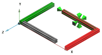
The command is only active if the cursor is on the part. The rotation center is moved to the current position of the cursor during activation. When turning and starting the Animation turning only occurs around the rotation center.
-
The following image shows the sub-menu of Views.
6 axis related perspectives as well as one Iso-, Di- and Trimetric view can be selected.
... turns a part with the marked face frontal (perpendicular) to the viewer.
--> Part turns to the front with the selected face.
opens the window Set rotation. Enter a numerical value and click on the appropriate "axis button". ---> The rotation is automatically carried out in 3D.
-
Select axis and distance of the cutting plane to the axis. Depending on prefixes a movement in positive or negative direction occurs. This entry is transferred to the 2D derivation
-
-
Aside from the assembly, you have the command Assembly -> Transparency available.