Manual
Login
Our 3D CAD supplier models have been moved to 3Dfindit.com, the new visual search engine for 3D CAD, CAE & BIM models.
You can log in there with your existing account of this site.
The content remains free of charge.

Top Links
Manual
 |
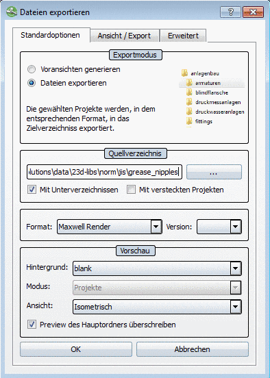
This section explains the export of image formats.
The following formats are available:
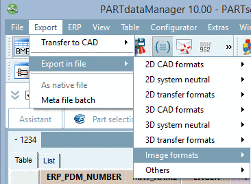
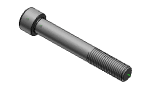
You can export the part displayed in the part view in several image formats.
The export dialog boxes of BMP, GIF, JPEG, PNG and TIFF format are nearly identic, the differences are marked.
BMP: "Attributes" tabbed page
GIF: "Attributes" tabbed page
JPEG: "Attributes" tabbed page
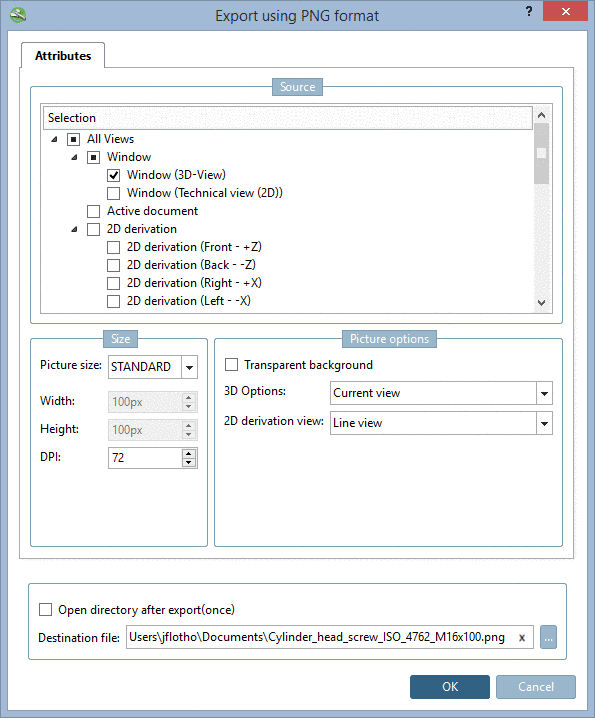
PNG: "Attributes" tabbed page
TIFF: "Attributes" tabbed page, "Tiff options" tabbed page
-
You can export all listed views or only the specially activated ones. Select a mode:
-
-
Detailed information on this is found under Section 3.1.1.11.3.1.2.1, “ Render mode ”.
-
Via Browse define the destination file.
Optionally activate the Open directory after export(once) checkbox.
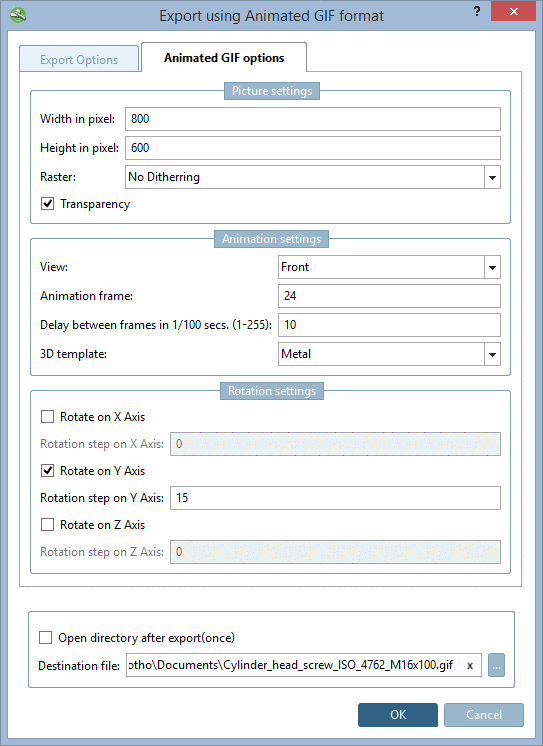
On the Animated GIF options tabbed page, you can find the following settings options:
-
![[Note]](/community/externals/manuals/%24%7Bb2b:MANUALPATH/images/note.png)
Note Please note the interdependency with the settings under Rotation settings.
If you set the rotation increment to 1°, you need 360 frames per rotation, so that a full rotation can be done.
-
Delay between frames in 1/100 seconds (1-255)
The rotation speed comes from this setting and the Animation frame setting.
-
You can adjust the color style to the layout of PARTsolutions versions, CAD systems and other style templates:
8.1, 9.0, Purist, Metal, Wood, Catia V5, Solid Edge, SolidWorks, NX, One Space Designer, Pro/Engineer, Inventor
Optionally you can define the rotational increment in degrees for the individual axes.
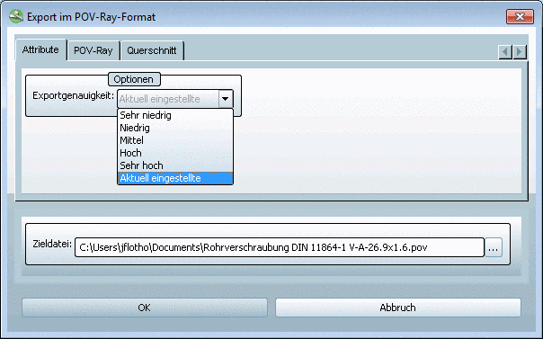
On the Export options tabbed page you can adjust the Export accuracy.
Select the desired accuracy in the list field:
The part is calculated with the set level of detail before the export.
The function is
identic to the level
of detail option 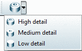 in PARTdataManager, but here only
temporarily for the export.
in PARTdataManager, but here only
temporarily for the export.
The following explains the settings dialog in detail:
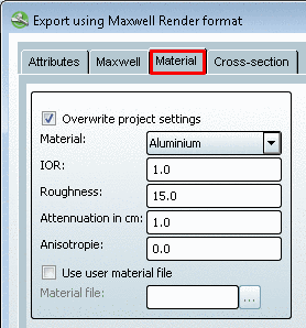
On the Attributes you can determine the Export accuracy.
In the list field select the desired accuracy:
The part is calculated with the set level of detail before the export.
This function is
identic with the level of detail option in PARTdataManager, but here only temporarily for
the export.
-
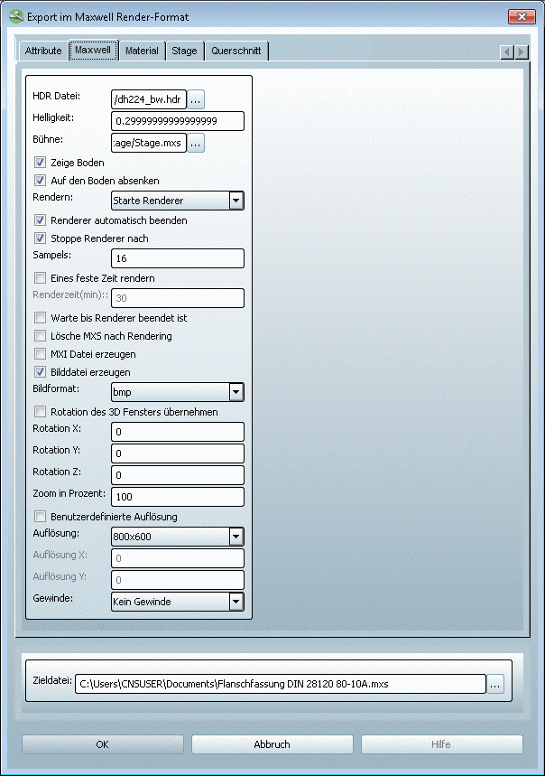
Basic settings for the lighting situation
Per default a file is already set up. Via Browse you may change the file. The Maxwell installation brings some sample files with it, which you may select here.
-
A default value is already assigned. Adjust the value if you like.
-
The stage on which the part is located, is already set up per default.
-
In the list field select the desired option:
-
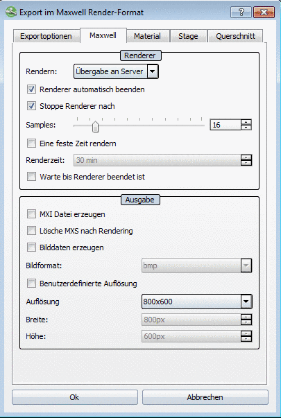
A *.mxs file is created without starting either the Renderer or the Studio. The file can later be opened in the Renderer or in the Studio.
Start renderer: Select this setting in order to create an image file.
-
When there is a server installation which you can access, select Transfer to server.
Then during the export the PARTrenderManager dialog box opens.
Via the PARTrenderManager you get additional options for rendering. A detailed description on this can be found under Section 3.1.2.1.2.4.3.6, “PARTrenderManager with Maxwell Renderer ”.
-
Quit after rendering: Closes the Renderer after the image file was created
-
Stop renderer after: Setting for the sample run-through (editing steps)
The more editing steps are carried out, the more accurate will the details be displayed.
-
Here you can determine the sampling rate. If no sampling rate is entered, the value is automatically set on 10.
-
If you do not want to edit the MXS file later in the Renderer or Studio you can delete it.
-
This file saves the render status up to date, so that you can later carry out more sample run-throughs.
-
The following image formats are available for use in the selection listg: bmp, tga, jpg, png, png (transparent), tif, jp2, exr, ppm, pbm, pgm, hdr
-
If you do not activate the checkbox, then you may define the rotation with your own values.
-
If you do not activate the checkbox, you cannot define your own values under Resolution.
-
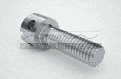
Threads: No threads, Only outer threads, Only inner threads, Only visible threads, All threads

|
|


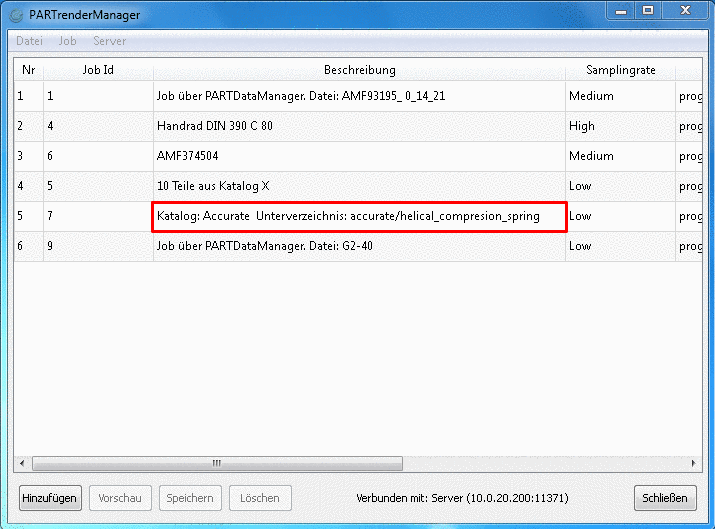
The PARTrenderManager enables to create images on a central server, so that different workstations can access.
Server and Client application are combined in one program. The first transfer parameter ("-server" or "-client") defines the program's functionality.
For the server a directory is needed, where the temporary files are stored. This directory has to be declared by a global variable with the name "PRM_TEMP"!
The client needs some data from the configuration file
prendermanager.cfg, which should be inside the directory "$CADENAS_USER". If this file is not existing at the first start there, the program will create a configuration file with default values.The program used for the image calculation (here the Maxwell Renderer), has to be already installed!
The user interface main component is a list, where all jobs of the currently connected server are displayed.
This list is automatically updated in a certain interval. Below the list you see some buttons to create or delete jobs for example. In addition you can call these functions via the job menu.
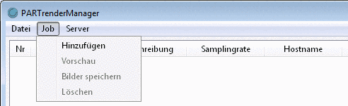
Furthermore beside the buttons information concerning the connected server or the file transfer are displayed.
The single orders from clients to the server are called "Jobs". These jobs contain the following data:
-
Already finished jobs (information on this transferred by the server) are displayed at the first positions. Then the currently processed job is displayed, and finally the waiting jobs, which not have been calculated images yet. The index numbers the complete list serially and is only important for the waiting jobs, because the sequence can be changed by it. The index number can be changed by double-click and in this way a job can be moved upwards in the list, so that the job is earlier processed by the server.
Index Job User 7 job1 finished job of C 8 job2 finished job of C 9 job3 this job is currently processed by the server 10 job4 A 11 job5 A 12 job6 B 13 job7 A 14 job8 A 15 job9 A 16 job10 B In this example user A can move job9 maximally to index number 13, because job6 belongs to another user. Job5 can be moved maximally to the index number 10, because otherwise it would be higher than the currently processed job.
-
This number serves for the job identification and is assigned by the server to each new job, which is delivered by a client. The ID has no relation to the index or the sequence and cannot be changed when a job is created.
-
The description helps to understand the content of jobs and to recognize jobs. Via double-click on a description it can be changed subsequently. However it is only possible as long as the job has not yet been processed and belongs to the respective user.
-
The sampling rate determines the number of runs the renderer can perform to calculate the images of a job. The higher the value the more exact the calculation and so the image quality. A high value results in a long calculation period for each image. After the creation of a job this value can be adjusted by a double-click. As with the description there is the restriction that it concerns the user's job itself and the job is still in the waiting line.
-
The status signalizes whether there is still a job in the waiting line or is currently processed by the server or is already finished. At finished jobs the number of images is displayed in addition. At the currently processed job the number of already finished images and the total number is displayed.
![[Important]](/community/externals/manuals/%24%7Bb2b:MANUALPATH/images/important.png)
In the menu Server all available servers, which are loaded from the configuration file, are displayed. The server connected to the client is marked. Via click on another server it is tried to change the connection to that server. When you want to add a new server to the list, click on then menu item Add server... A dialog box opens. In this dialog the needed information (IP address, port and name) has to be entered. Thereby it is automatically checked whether the server name is unique and differs from the already existing server. A click on the button checks, whether a connection to the server is possible. This test is automatically processed before the adding of a server, if the connection has not been checked before. Only a successful test results in adding the server to the list. Furthermore you can define, whether the client shall immediately connect to the new added server. After a successful creation of the server its data is saved in the configuration file.
You can call up the PARTrenderManager in different ways:
via PARTdataManager -> menu Export -> Export in file -> Image formats -> Maxwell Render -> Maxwell Renderer tabbed page-> Render menu item -> selection Transfer to server
-
via PARTdataManager -> context menu of a directory/project in the index tree -> Generate image data/preview images -> Maxwell Render -> Maxwell Renderer tabbed page -> Render menu item -> selection Transfer to server
More information is found under Section 3.1.2.1.2.4.3.6.2.4.3, “Create job in PARTdataManager via Generate image data/preview images ”.
The creation of jobs in the PARTrenderManager (Client) happens in the Create a job dialog box.

-
Select the desired sampling rate in the list field.
Preview images showing the different qualities will help to choose an adequate sampling rate.
At this value choose an adequate compromise between quality and needed creation time.
When all settings are done, click on the button . The data is sent to the server now.
If the files are located in different folders they have to be added to the file list separately! When the finished images are resaved PARTrenderManager keeps the folder structure.
The job contains the following files:
C:/FolderA/File1.mxs
C:/FolderA/FolderA1/File2.mxs
C:/FolderB/File3.mxs
C:/FolderB/File4.mxs
If as target directory that path which all files have common (here in the example this would only be „C:/“) is set for the resaving, then the images are saved to their respective .mxs files.
C:/FolderA/File1.mxs
C:/FolderA/File1.bmp

C:/FolderA/FolderA1/File2.mxs
C:/FolderA/FolderA1/File2.bmp

C:/FolderB/File3.mxs
C:/FolderB/File3.bmp

C:/FolderB/File4.mxs
C:/FolderB/File4.bmp
If another target directory is set, then the folder structure is also kept (only the common path changes).
Target directory shall be: D:/Images/
C:/Images/FolderA/File1.mxs
D:/Images/FolderA/File1.bmp

C:/Images/FolderA/FolderA1/File2.mxs
D:/Images/FolderA/FolderA1/File2.bmp

C:/Images/FolderB/File3.mxs
D:/Images/FolderB/File3.bmp

C:/Images/FolderB/File4.mxs
D:/Images/FolderB/File4.bmp
The mxs files are still under "C:/" (thus exactly in the origin paths), only the images are saved under "D:"!
Via Export in file (a single file) a job can be created directly from PARTdataManager and transferred to the server.
After a part has been loaded in the Part view, start the export via Export menu -> Export in file -> Image formats -> Maxwell Renderer.
-> The Export using Maxwell Render format dialog box opens.
Settings in the Export using Maxwell Render format dialog box:
A description on all other settings is found under Section 3.1.2.1.2.4.3, “Maxwell Render 3D ”.
-> After confirmation with the job is sent to the PARTrenderManager Client and the PARTrenderManager dialog box opens. The job appears in the dialog box. The Create a job dialog is not called. The description is automatically created. The sampling rate can optionally be changed as long as the job is in the waiting line, meaning the job status is "Waiting". The list of jobs cannot be changed anymore.
|
|
|
The *.mxs files are created and a job with paths to all project files is generated and sent to PARTrenderManager.
|
Note |
|---|---|
|
During the generation there are no previews available (neither the old ones, nor the new ones). [81] | |
If you had selected Start renderer, then the new preview images are available as soon as the renderer has finished.
If you had selected Transfer to server, then the new preview images are available when these have been downloaded from the server and been resaved.
In the dialog box of PARTrenderManager you can see under description, for which directory the preview images have been created. Resave these in the respective directory (directories), when the job has finished.
When you want to delete one or more jobs, then select the respective jobs from the list and click on the button .
Jobs from other users, which are also selected, will not be deleted.
When deleting the current job the following has to be regarded:
The renderer can not be stopped by the server, meaning that the renderer will finish the calculation of the current image in any case. When the job is deleted during the calculation no calculation of a new image will be started by the renderer and the next job in the waiting line is processed. So it can happen, that the list of the client contains no job, which is currently processed by the server.
It is possible to request the current status of the image as preview during the calculation:
For calling the preview image there are several ways:
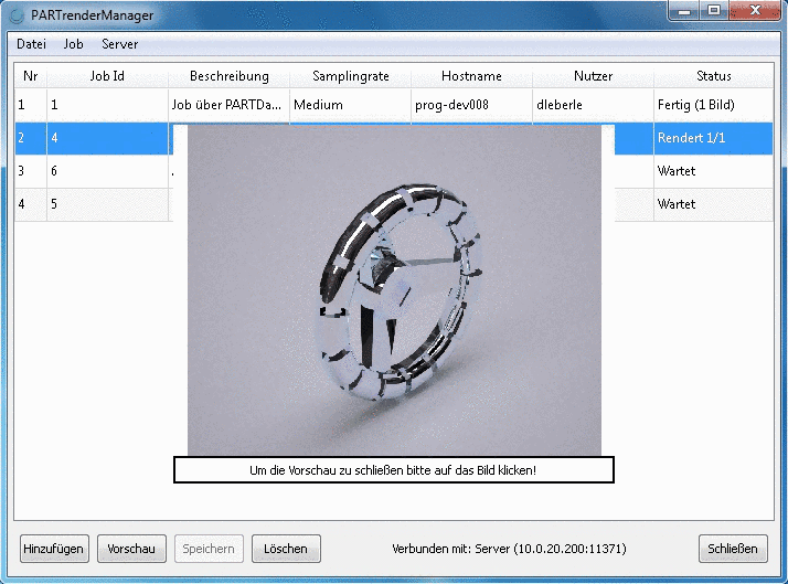
The preview image is displayed on the client and can be closed with a click on the image.
As soon as the renderer has calculated all images of a job, the job is marked as finished and the images can be downloaded to the client computer. Thereto you only have to select a job and click in the job menu on Save images. Alternatively you can click on the button or use the respective context menu command of the respective job line.
When the files from which the images have been calculated are from different folders, then the folder structure is regarded at saving.
Basically
each user has only the authority to change or delete jobs of his own.
When resorting his waiting jobs he cannot place them before other users
jobs. However there is the possibility to extend the user rights. In the
configuration file $CADENAS_USER/prendermanager.cfg in
the section "global" you can find a key "role". If you set the value to
"Admin" and restart the client you can change, delete or resort all jobs
without restrictions.
Use the POV-Ray 3D with raytracing[82] and photo realistic computer graphic for the 3D display.


Prerequisites for using the POV-Ray export format

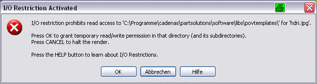
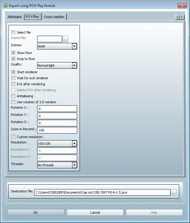
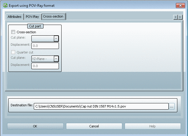
When opening the export format under PARTdataManager -> Export menu -> Image formats -> POV-Ray, the tabbed page POV-Ray format shows up with the Attributes, POV-Ray and Cross-section index pages, which are described below.
-
Select file to define the scene
The following scenes are made available in the selection list:
Show floor Compare example Fig. „Steel“.
Drop to floor: Compare example Fig. „Steel“.
-
To control the light reflection, you have the following settings:
Normal light, Low radiosity, Medium radiosity, Hight radiosity
-
Usually you leave this option in an deactivated state.
This function is needed for batch exports in order to prevent several renderers from being started at the same time.
-
If you do not want to edit the POV file later in POV-Ray, you may delete it.
-
If you do not activate the checkbox then you can define the rotation with your own values.
-
Values less than 100 zoom out of the image, greater ones zoom in.
-
If you do not activate the checkbox, then you can define your own values under Resolution.
When you activate the option, then enter your desired resolution under Resolution X and Resolution Y.
-
Threads: No threads, Only outer threads, Only inner threads, Only visible threads, All threads
POV-Ray can also be used to create previews. See Section 3.1.3.3.1.3, “ Generate image data/preview images ”.