Manual
Login
Our 3D CAD supplier models have been moved to 3Dfindit.com, the new visual search engine for 3D CAD, CAE & BIM models.
You can log in there with your existing account of this site.
The content remains free of charge.

Top Links
Manual
 |
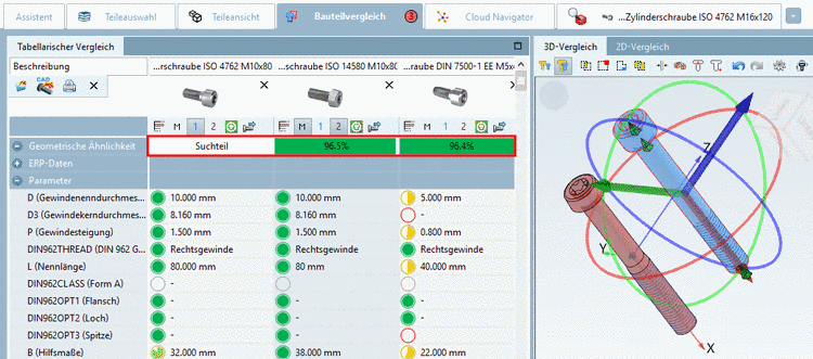
The Tabular Compare shows information on ERP data, data of characteristic attribute table, topological information and classification data.
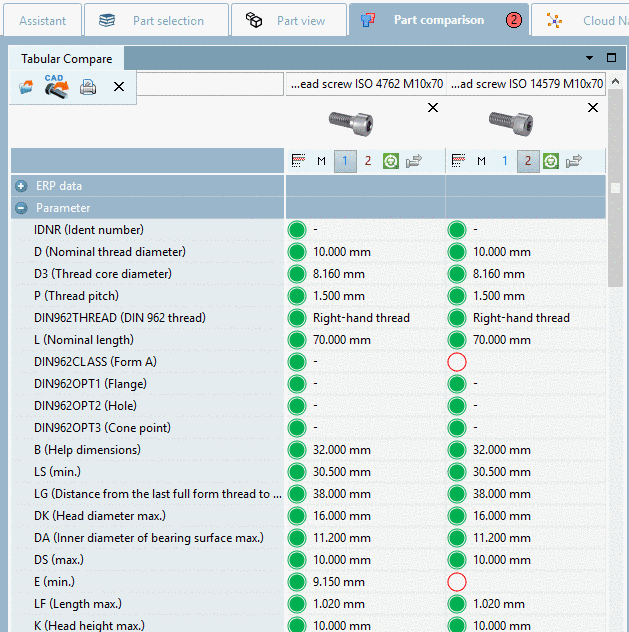
Geometrical similarity (if a Geometric search (3D) has been performed before)
-
Topology (all attributes relevant for the parts to compare are displayed)
![[Note]](/community/externals/manuals/%24%7Bb2b:MANUALPATH/images/note.png)
Note The quality of topological information/features depends on different factors. On this see below.
-
Classification data (all installed classifications are displayed)
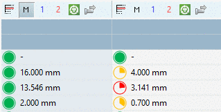
The pie charts mirror the percentage similarity of values.
Colored markings of searched topological parameters
Topological parameters are color-marked so that you can see the most important ones at a glance.
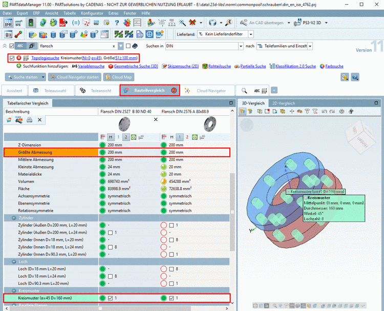
Explicitly searched topological attributes are marked in color.
-
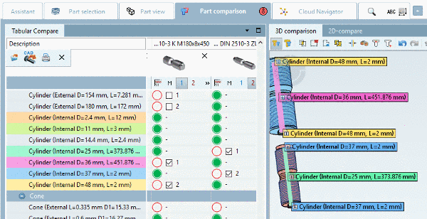
Those topological parameters which can be marked in the 3D view (Circular pattern, Inner cylinders, Outer cylinders), have a checkbox in the listing under Tabular Compare.
If you activate a checkbox then the respective parameter is color-marked both in the Tabular Compare and in the 3D comparison. Different parameters get different colors (regardless of whether they have been automatically or manually marked)
In the column header you can find the following icons:


At parts, which are found via Geometric search (3D) and are transferred into the Part comparison, there, in the Tabular Compare section the geometric similarity is overtaken and displayed as well.[69]

Open: Right-click anywhere in the desired column.
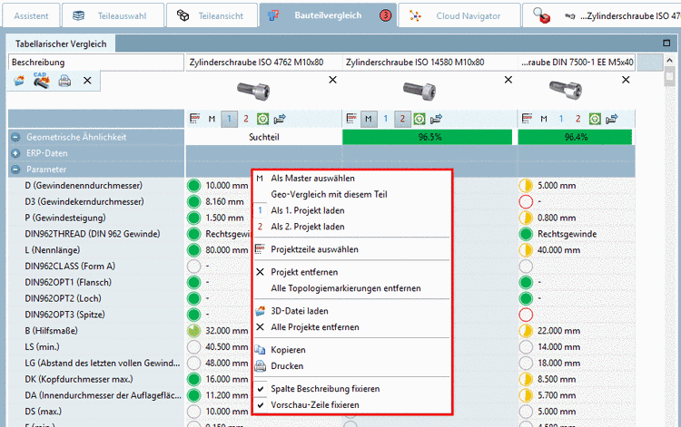
In the context menu the following commands are available:
-
Select as master [compare icon above
 ]
]The corresponding column is displayed with a green background color.
-
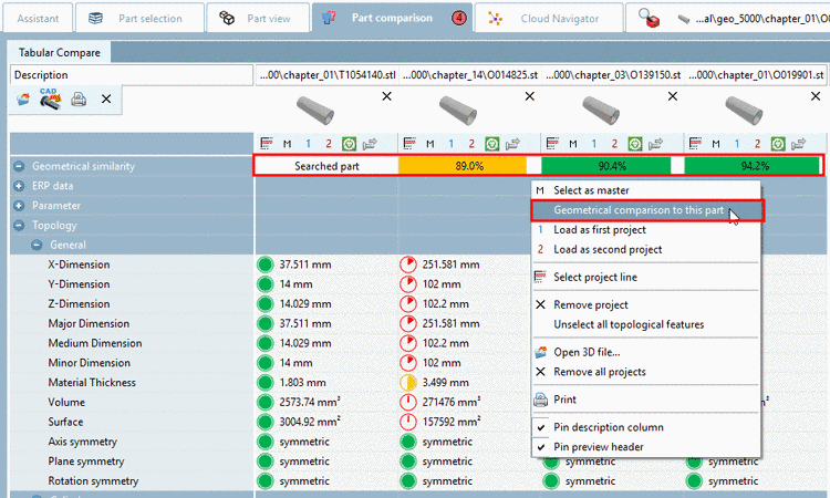
Geometrical comparison to this part:
Initial situation: Displayed percentages of geometrical similarity can be calculated by processes executed before or they haven't been calculated yet.
Regardless of this you can start a new calculation for each part in the part comparison separately.
Hereto call the context menu command Geometrical comparison to this part on the desired part. The search part (100%) is marked as such.
-
Select project line [compare icon above
 ]
]Switches to the row view (see following figure)
By clicking on , the display changes to the export state.
For a logical 3D comparison, change the properties so that the compared parts possess about the same dimension.
-
Unselect all topological features
(Markings are set according to the used search parameters.)
Colored markings in Tabular Compare (see Fig. „ Tabular Compare - Context menu commands“) and labels in 3D view are removed.
-
Load any native file (specific CAD file or neutral format) in the Compare dialog.
The same function is also available via button Open 3D file...
 . A description can be found below.
-
Pin description column | Pin preview header
In order to keep in view the important during vertical and horizontal scrolling, it possibly makes sense to fix the column "Description" [horizontal scrolling] or the preview line [vertical scrolling].
In the Tabular Compare section call the context menu and activate the desired option.

-
-
Click on the menu item Open 3D file...
.-> The dialog box Load native cad file is opened.
-
A variety of formats can be opened: [70]
-
Note In STEP format topology information/features is loaded in best quality (if the license "PSADDONS*ADVANCEDTOPO" is available).
Sphere, Torus and Elongated Cylinder are available in addition. All other features are read in with much higher quality.
Also see Section 3.1.6.10.2.1, “Quality of topology information/features”.
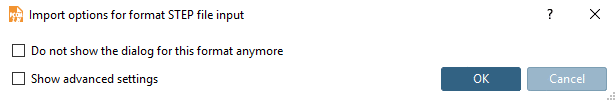
When using the STEP format the dialog box Import-Optionen für Format STEP file input is opened.
-> The dialog box Load native cad file is opened with the following message:
"The CAD file was added to part compare. Load the part as the first or the second project to load it in the 2D/3D view."
Confirm with .
-
If there is an ambiguity for a file extension, an additional dialog box appears.
Ambiguities are possible for a file extension such as
.prtfor example, which is used by Creo Elements and NX as well, furthermore for several versions of a CAD system.In the list field select the desired system and the desired version.
-
Then the dialog box Selection of unit is opened.
In the list field, select the correct unit: mm, cm, dm , m, INCH, FEET, INCH/10, INCH/100
-
-
When clicking on Load geometry from CAD
 , the part or assembly selected in CAD is loaded
in dialog for searching.
, the part or assembly selected in CAD is loaded
in dialog for searching.


[69] You can configure, whether the geometric similarity shall be displayed. See Section 1.7.4.5.2.1, “ Key "DisplayGeoDistances" - Tabular Compare - Display geometric similarity ” in PARTsolutions / PARTcommunity4Enterprise - Administration Manual.
[70] The number of displayed formats depends on the installed CAD systems.
