powered by CADENAS

Manual

Manual

3.1.12.3. Small example from A to Z

Initial situation:

You want to join two plates with a connection.

Do the following:

2 plates

2 plates

  1. Launch

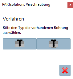
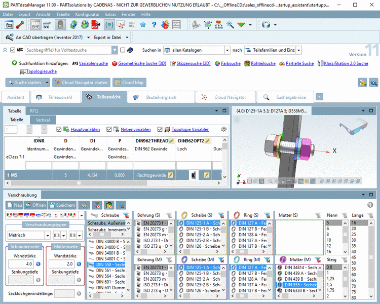
    In the PARTsolutions menu of your CAD system click on Insert Connection.

    [Note] Note

    The button for calling the function from CAD menu is hidden by default.

    [Note] Note

    For the very first time you launch Connection, all possible connection elements are indexed. You can notice this when looking at the status bar.

    -> The PARTsolutions Connection dialog is opened.

  2. Click on the desired option.

    • Blind hole

    • Through-hole

    Select Connection type

    Select Connection type

    -> The respective information for selection is displayed.

    Info and demo for determining wall thicknesses at a blind hole

    Info and demo for determining wall thicknesses at a blind hole

    Info and demo for determining wall thicknesses at a through hole

    Info and demo for determining wall thicknesses at a through hole

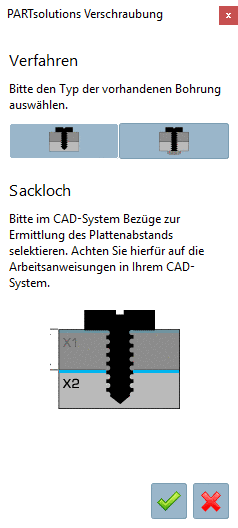
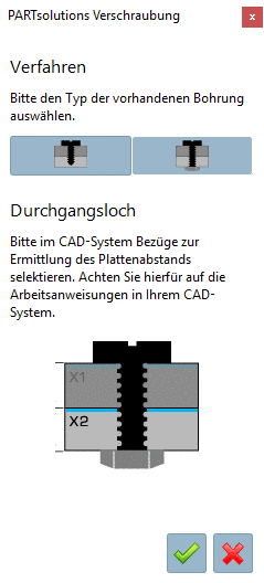
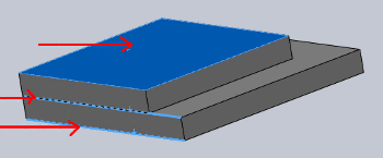
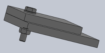
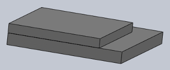
  3. Choose the best elements for the definition of the distance (normally with the help of Ctrl key).

    The figure shows the selection of a plane and two edges.

    The figure shows the selection of a plane and two edges.

    Per cursor, you can capture corners, edges or parallel Layers (wall thicknesses) of the elements to be connected, as well as the Insertion point of the connection. Depending on whether you want to insert a through hole or blind hole boring, you must determine the required reference planes on the surface of the selected elements.

    Finally click on the green checkmark.

    -> The application switches to PARTdataManager.

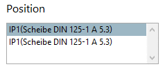
  4. In PARTdataManager, determine the desired connection elements.

    PARTdataManager with section "Connection"

    PARTdataManager with section "Connection"

    Detailed information on this can be found under Section 3.1.12.4, “User interface in detail ”.

  5. Boring with export?

    This option determines if the holes are exported as actual parts.

    [Note] Note

    Whether the corresponding holes (through hole/blind hole) are also created depends on the respective CAD system (see Section 2.5, “CAD specific menu commands and information ”).

  6. Then click on the button, or the menu command under Export -> Transfer to CAD.

    The export of a Connection to your CAD system occurs analogously to the way parts and assemblies are transferred. See Section 3.1.8, “ Export to CAD (with and without interface) ”.

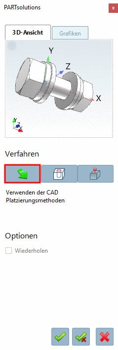
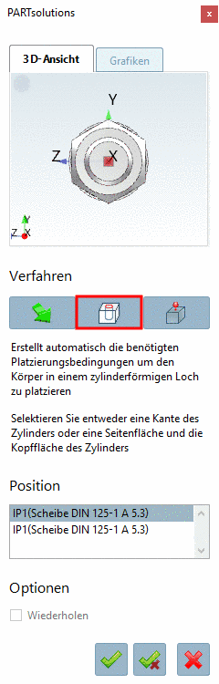
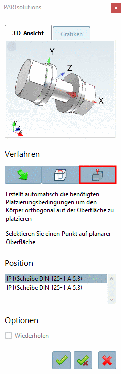
    -> The view returns to the CAD system and the placement dialog is opened.

  7. Choose the placement method.

    Placement with the methods of CAD system

    Placement with the methods of CAD system

    Placement directly in the cylinder boring

    Placement directly in the cylinder boring

    Placement via point on plane

    Placement via point on plane

    • Use CAD placement methods

    • Create mates for placement on cylinder hole

      Please select a edge on a cylinder or the top and side surface of an cylinder.

    • Create mates for placement on planar face

      Select a point on a planar surface

  8. Choose the Position.

    According to selection the corresponding connection point is displayed.

  9. Click on one of the following buttons:

    • Place multiple

      -> The placement is executed and dialog remains opened.

    • Place once

      -> The placement is executed and dialog is closed.

    • Close dialog

      Dialog is closed without placement.

  10. Result

    Connection placed

    Connection placed