Manual
Login
Our 3D CAD supplier models have been moved to 3Dfindit.com, the new visual search engine for 3D CAD, CAE & BIM models.
You can log in there with your existing account of this site.
The content remains free of charge.

Top Links
Manual
 |
In the following the characteristics / modeling rules will be described for each target system:
The parts must be located with the Z-axis to the top and with the Y-axis to the front (left in the isometric view)
The parts require the Placement Classification (see Section 5.9.2.4, “ Published element - Choose connection point ”)
The parts should be equipped with a changeable Level of Detail (also see below)
![[Note]](/community/externals/manuals/%24%7Bb2b:MANUALPATH/images/note.png)
-
The parts must be classified with “Revit-Family-Templates” and “OmniClass 2006” (on this see separate point Classification below).
It is not allowed to use features / radius smaller than 1.4mm in modeling.
Use extrusion features and avoid rotation features - if possible.
-
Cut-rotations (e.g. chamfers) should also consider the 1.4mm tolerance
All kind of conductors, pipes, channels, etc. have to be modeled as “filled body” absolutely.
-
A REVIT placement point (Revit-Family-Template-Mapping) must be specified (please also see separate point Classification below).
For the placement in REVIT the axes of the REVIT placement point will be used for positioning /orientation. Take care that axes orientation of the point is according to the axes in REVIT (Z on top is recommended).
-
REVIT connection points always have to be in the geometric center of gravity of a planar surface (please also regard the orientation of the Connection Point).


-
The parts must be classified with IFC4
(See separate point Classification below.)
Use extrusion features – Avoid rotation features - if possible.
-
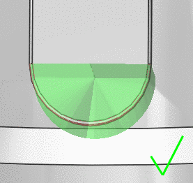
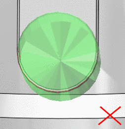
Absolutely avoid cut of edges (single edges should not touch each other):
-
It is not allowed to subtract volumina more than 1 time (cut features should not touch each other).
All parts should be tested with the “IfcCheckingTool”, see Further tests below.