powered by CADENAS

Manual

Manual

13.3.1. Configuration

The following example shows how a configuration is constructed step-by-step and individually in the PARTdataManager.

[Note] Note

You can follow the example if you have installed the training.cip.

(Training/assembly/hinge/hinge_asmcfg.prj)

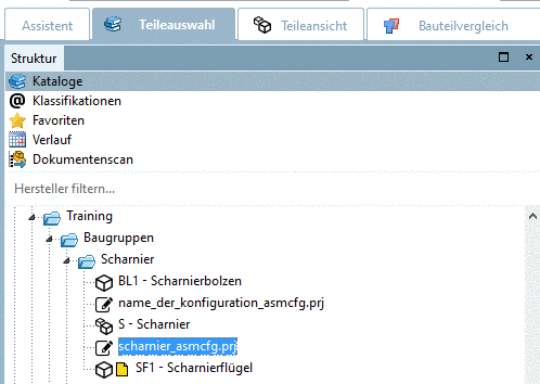
  1. In the PARTdataManager Part selection select a configuration.

    [Note] Note

    Here in this example, during project application, a name convention (configuration add-on of "_asmcfg" in the name) was used.

    Configuration - asmcfg.prj

    Configuration - asmcfg.prj

  2. Open the configuration with a double-click.

    First, in the Assembly area in the Tree view only the Description is shown and the Option list remains empty.

    The configuration elements are already applied, however they still need to be selected and/or activated.

  3. Start element insert

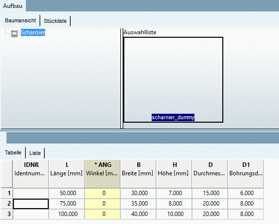
    Click on the Description (here in the exemplarily figure "Scharnier").

    -> The Start element of the assembly is shown in the Option list.

  4. You can insert the displayed element in two different ways:

    • Open the corresponding context menu (right mouse-click) and select the part to be inserted (in this example "scharnier_dummy")

      or

    • click into the Option list on the designated element (in this example "scharnier_dummy").

    -> The table is displayed.

    [Note] Note

    If there are several table rows available for parts, you can change the characteristics. The display in the 3-D preview is automatically adjusted.

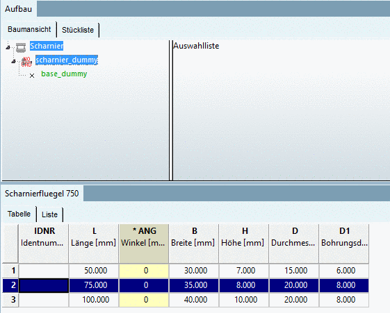
  5. In the table, select a characteristic.

    -> Now in the Tree view, the insertion point of the start element (here "base_dummy") is displayed.

    Start element not yet specified

    Start element not yet specified

  6. Click on the insertion point.

    -> In the Option list, the part is displayed.

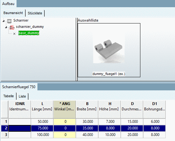
  7. In the Option list, click on the part.

    -> The part is displayed in the 3D view.

    -> In the Tree view, more parts and insertion points are displayed.

  8. Click on the next insertion point (here "mitte").

    -> Further possible parts are displayed in the option list.

    [Note] Note

    In the Tree view below the parts you can see - as long as there remain connection parts - the possible Connection points. These are displayed as small green pyramid symbols in the 3D view.

    At each connection point assembly components from the Option list can be added.

    The insertion points in the Tree view are color-coded:

    • Green: A part may be added.

    • Yellow: A part is already added but another one may be added as well.

    • Black: A part is already added and another one may not be added.

    With the described way you can insert individual elements until all suggestions have been covered. Then there are only connections with black font.

  9. One by one, click on the offered insertion points of parts, as long as the configuration is completely assembled.