Manual
Login
Our 3D CAD supplier models have been moved to 3Dfindit.com, the new visual search engine for 3D CAD, CAE & BIM models.
You can log in there with your existing account of this site.
The content remains free of charge.

Top Links
Manual
 |
With the help of a small example the working when creating a new dimensioning shall be shown.
A horizontal dimensioning shall be created for a hole diameter.
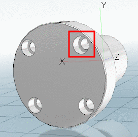
In PARTdataManager, in the Part view, load the part to be dimensioned.
-
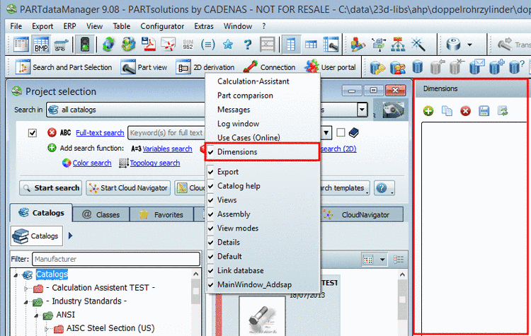
In PARTdataManager, open the dialog area Dimensions by clicking on the same-named command in the context menu of the toolbars.
-> The dialog is displayed as docking area. You can detach the area via drag and drop so that it is displayed as a single window.
-
Make sure that dimensionings are displayed in the 3D view.
Therefor, in the toolbar of the 3D view, click on the button Show Dimensions
 , if needed.
 -
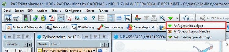
Make sure that the connection points are displayed in the 3D view.
Therefor, in the toolbar Montage, click on the button Show connection points.
-
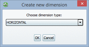
Click on the button Create new dimension
 .
.-> The respective dialog box opens.
In the list field, select the option HORIZONTAL and confirm with .
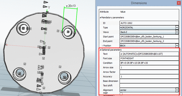
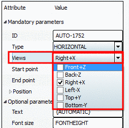
-> In the upper half of the dialog area Dimensions a new ID is automatically created.
-> In the lower half of the dialog area Dimensions all corresponding parameters are displayed.
-
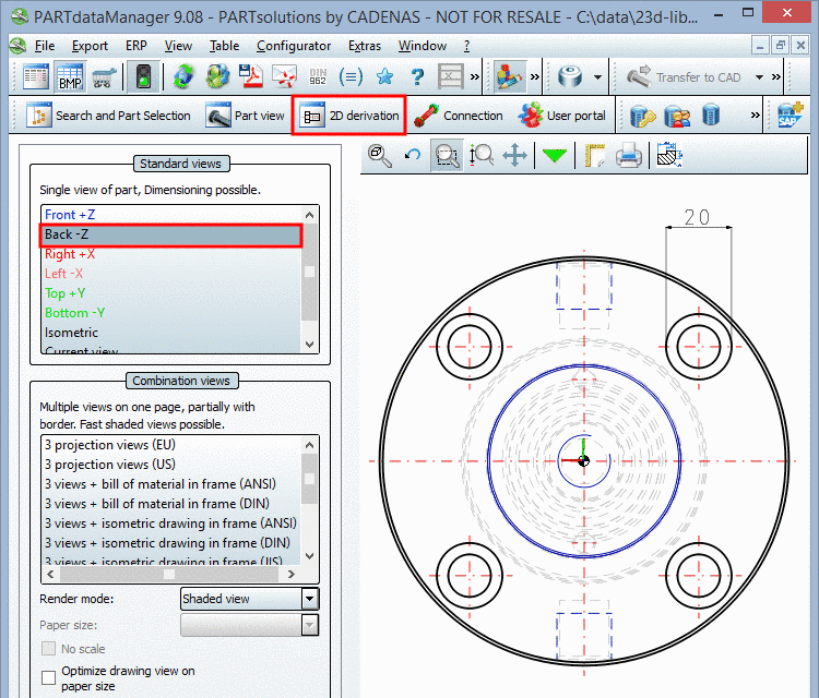
Under Mandatory parameters -> Views select the desired 2D view(s), where the dimensioning has to be displayed.
-
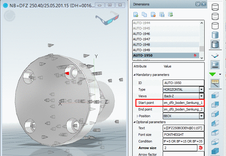
Now determine the Start point of the dimensioning.
-
Click into the input field of Start point and enter the name of the connection point via Ctrl+V from the clipboard.
-
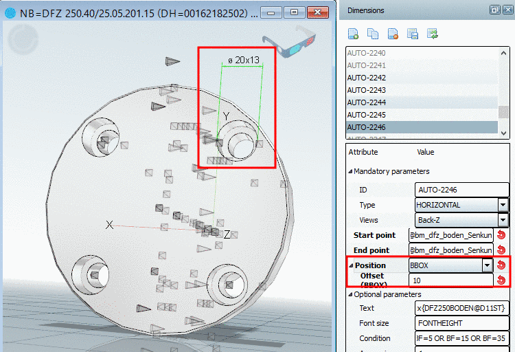
In the list field of Position, select the value BBOX (Bounding box) and under Offset (BBOX) enter the value 10.
-> As soon as all Mandatory parameters are set, the dimensioning is shown in the 3D view.
-
If needed, you can modify Optional parameters (e.g. Text) or set (e.g. Arrow size).
A complete summary of all PARTdesigner expressions can be found under Section 7.8, “Functions - PARTdesigner-Expressions ”.
-
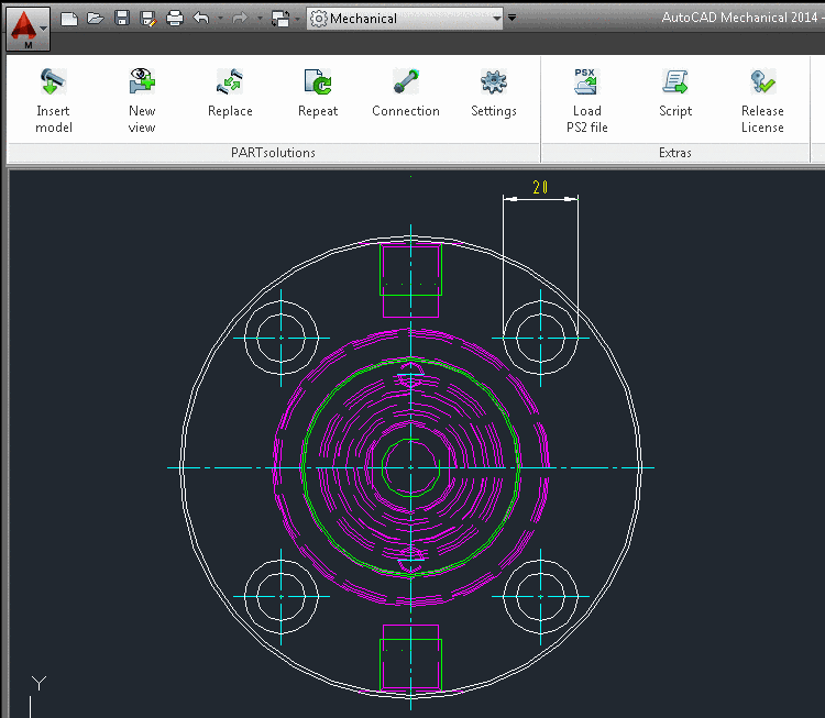
When exporting to the CAD system the dimensioning is transferred as well.
![[Note]](/community/externals/manuals/%24%7Bb2b:MANUALPATH/images/note.png)


![[Tip]](/community/externals/manuals/%24%7Bb2b:MANUALPATH/images/tip.png)