Manual
Login
Our 3D CAD supplier models have been moved to 3Dfindit.com, the new visual search engine for 3D CAD, CAE & BIM models.
You can log in there with your existing account of this site.
The content remains free of charge.

Top Links
Manual
 |
The parts created in PARTdesigner can be configured to assemblies with the Configurator.[63]In order for this to happen, the parts in PARTdesigner must be assigned precisely defined and named insertion and connection points .
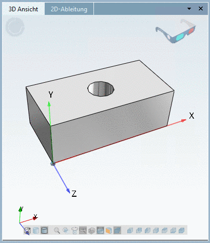
A cuboid contains a boring into which a screw is to be inserted later (assembly configuration). Therefore a connection point needs to be applied for the boring.
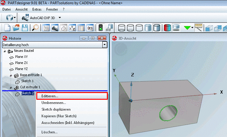
Click on the Face, in which the boring is to be applied. --> The according Sketch shows up in the History highlighted in color.
-
Right-click on the context menu of the sketch (in this example, Sketch 2).
-
"Catch" the center of the circle (boring) with your cursor and affix it with a simple mouse-click.
--> The point gets a green triangle symbol .
--> The Change parameter window opens.
Assign a name to the connection point - for example: CP1 - and confirm with .
Optionally, you may make changes in the other fields as well.