powered by CADENAS

Manual

Manual

6.9.3.2.2.2. Create rotated pattern

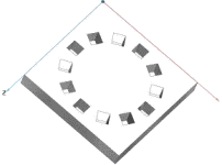
The creation of a rotated pattern corresponds to the method of creating a pattern with equal orientation (see above).

[Note] Note

A round assignment of a boring series can be reached by a pattern with equal orientation. For a rotated pattern the borings are centered on a specific reference point (button Reference point for rotated pattern ).

To clarify a rotated pattern the following is explained step-by-step.

Pattern: round borings

Pattern: round borings

Pattern: angular borings

Pattern: angular borings

Rotated pattern: borings centered on point of origin

Rotated pattern: borings centered on point of origin

6.9.3.2.2.2.1. Create pattern with circular orientation

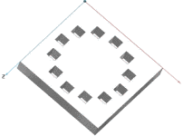
The starting basis for the following commentary is a boring that is to be duplicated 12 times.

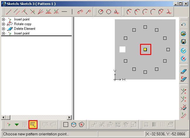
  1. Via the button Choose new pattern origin... set the pattern origin on the desired boring.

  2. Via Generate sketch on selected face. set a new sketch for the pattern.

    [Note] Note

    Set the sketch for the pattern points on the same level as the sketch with the pattern origin.

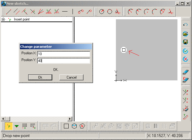
  3. In this sketch, set the point of origin for the construction of the pattern at the same place as the point of origin in the other sketch is located.

  4. Mark the point.

    --> The copy commands show up.

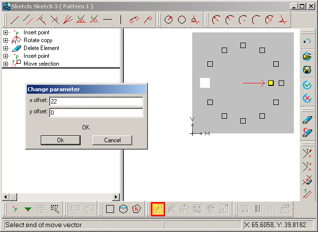
  5. While holding down the CTRL button, select the button Rotate selection .

    Follow the instructions in the status row:

    • Choose rotation point

    • Choose angle by point

    • Choose rotation angle by point

    --> The dialog window Change parameter opens.

  6. Adjust the values in the input fields Number, Rotation point and Angle of rotation and confirm with OK.

  7. Delete the basis point since otherwise it will be created twice (it can be found as the Pattern origin in the other sketch).

  8. Click on the button Accept changes .

    --> The sketch display is closed.

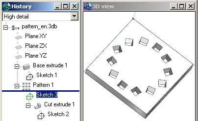
  9. In the History mark Cut extrude and the sketch, which contains the pattern (in this example Sketch 3) and in the context menu, click Create pattern .

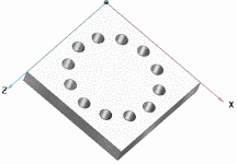
    --> The borings are multiplied according to the pattern.

6.9.3.2.2.2.2. Angular borings

In the sketch, delete the circle and replace it with a square.

The bore holes are now arranged in squares and circles (but still equally oriented).

6.9.3.2.2.2.3. Arrange borings to points of reference
  1. Open the sketch that contains the pattern.

  2. Insert a point in the middle of the pattern.

  3. Click on the button Reference point for rotated pattern and then on the point.

    --> The point of reference for the rotated pattern is now highlighted in yellow.

  4. Then click on the button Accept changes.

    The borings are now aligned on a point of reference.

6.9.3.2.2.2.4. Move point of reference of rotated pattern

For special applications it may be useful to move the point of reference.

  1. Click on Move selection .

  2. Click on the reference point to be moved.

  3. The movement vector is now attached to the cursor.

  4. Select the endpoint of the movement vector.

    --> The window Change parameter opens up.

  5. Adjust the values accordingly.

    The borings are aligned to the new point of reference.