Manual
Login
Our 3D CAD supplier models have been moved to 3Dfindit.com, the new visual search engine for 3D CAD, CAE & BIM models.
You can log in there with your existing account of this site.
The content remains free of charge.

Top Links
Manual
 |
In the right half of the window you can define the position of the assembly within the spatial display 3D preview and/or in the CAD system. This function is to be used for the new positioning of the entire assembly.

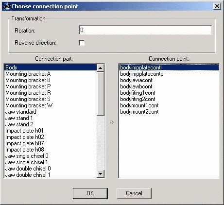
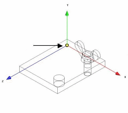
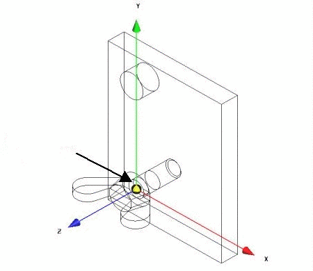
The assembly no longer positions itself according to presets (corner of plate at point of origin of coordinate system), but now according to the connection point Drilling 1 (see image).
Further explanations to Choose connection point :

Further explanations to Assembly properties :
You can connect the positions that you set in the Center point and in the fields X, Y, and Z via AND / OR as well.
|
For the combination of the positioning specifications with AND, both specifications are considered, in other words added. |


