Manual
Login
Our 3D CAD supplier models have been moved to 3Dfindit.com, the new visual search engine for 3D CAD, CAE & BIM models.
You can log in there with your existing account of this site.
The content remains free of charge.

Top Links
Manual
 |
In order to display the external chamfers on the cap nut hexagon, two angled lines, a vertical and a horizontal must be drawn in.
-
Angled line inclined to the left
Click the Line at angle to line with length button
 . Using this function you can create
Lines at any Angle to another line.
. Using this function you can create
Lines at any Angle to another line.Highlight the upper DK/2 as line of reference. --> The new line follows the cursor.
Move the cursor to the starting point (intersection point between upper horizontal line DK/2 and hex height M) of the angled line until the snap appears and fix it with a mouse click.
-
Dialog box Change parameter: Enter the angle 90+15 and the length 5.[3]

-
Angled line inclined to the right
Before you can draw in the second angled line, you need the Start point of the chamfer.
The position of starting point results from the intersection between y-axis and a further horizontal (distance DW/2).
-
Add horizontal line above the x-axis at a distance of DW/2 .
Again, click on the button Line at angle to line with length
and as line of reference highlight the axis
DW/2. --> The new line follows the
cursor.Lead the cursor to the starting point (intersection point between Y axis and the horizontal DW/2) of the angled line until the snap appears and fix it with a mouse click.
-
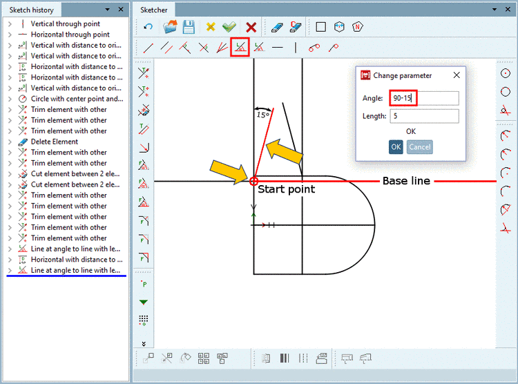
Draw an ascending line from the Start point to the right side and fix it with a single mouse click.
-
Enter the angle 90-15° and the length 5.
-

![[Note]](/community/externals/manuals/%24%7Bb2b:MANUALPATH/images/note.png)

