Manual
Login
Our 3D CAD supplier models have been moved to 3Dfindit.com, the new visual search engine for 3D CAD, CAE & BIM models.
You can log in there with your existing account of this site.
The content remains free of charge.

Top Links
Manual
 |
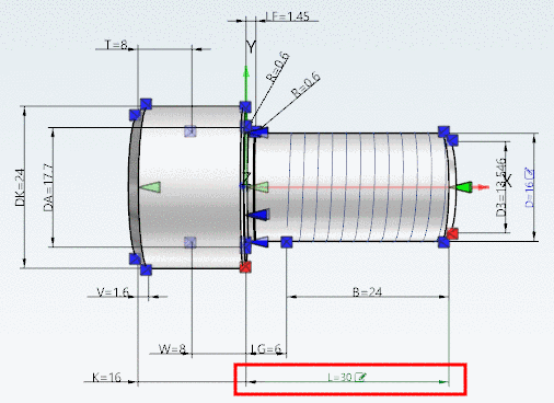
With the help of a small example the working when creating a new dimensioning shall be shown.
A horizontal dimensioning shall be created for the length of a bolt:
In PARTdataManager, in the Part view, load the part to be dimensioned.
Possibly activate the Configuration mode
 .[26]
.[26]
-
In PARTdataManager, open the dialog area Dimensions by clicking on the same-named command in the context menu of the toolbars.
-> The dialog is displayed as docking area. You can detach the area via drag and drop so that it is displayed as a single window.
-> Now the dimensioning points and connection points are displayed.
-
Make sure that dimensionings are displayed in the 3D view.
Therefor, in the toolbar of the 3D view, click on the button Show Dimensions.
-
Make sure that the connection points are displayed in the 3D view.
Therefor, in the toolbar Assembly, click on the button Show connection points.
-
Click on the button Create new dimension
 .
.-> In the upper dialog area a new line "AUTO"-... is added and below, under Mandatory parameters the Type HORIZONTAL is created by default. (In the example in hand this is correct. Otherwise adjust the selection in the list field.)
-
Under Mandatory parameters -> Views, select the desired 2D view(s), where the dimensioning has to be displayed. Here in the example Front+ Z.
Views which contain a dimensioning, can be recognized in the 3D toolbar by a respective icon with dimensioning lines
 .
. -
Now determine the Start point of the dimensioning.
-
Call the context menu and select Use as ... -> Start point.
-
Repeat the same procedure for the End point.
-
In the list field of Position, select the value BBOX (Bounding box) and under Offset (BBOX) the value -DIST*12 (here in the example).
-> As soon as all Mandatory parameters are set, the dimensioning is shown in the 3D view.
-
If needed, you can modify Optional parameters (e.g. Text) or set (e.g. Arrow size).
A complete summary of all PARTdesigner expressions can be found under Section 15.1, “PARTdesigner-Expressions ”.
-
Once the variable name is entered, the editing icon
 is displayed.
Later, the user can change the characteristic here. Compare Section 3.1.7.6.6, “Change characteristic via dimension labels ” in PARTsolutions / PARTcommunity4Enterprise - User manual.
Adjust the value for font size accordingly (here in the example "DIST").
-
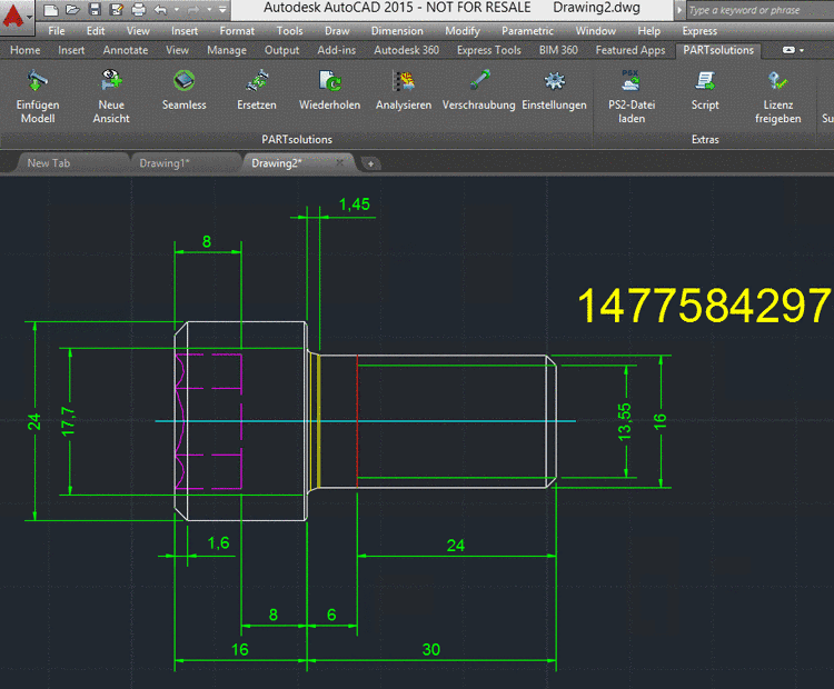
The set dimensioning is also used for the 2D derivation.
-
When exporting to the CAD system the dimensioning is transferred as well.


![[Tip]](/community/externals/manuals/%24%7Bb2b:MANUALPATH/images/tip.png)


[26] In some cases the Configuration mode has to be activated and PARTdataManager to be restarted, in order for the connection points and dimensioning points to become visible.
