Manual
Login
Our 3D CAD supplier models have been moved to 3Dfindit.com, the new visual search engine for 3D CAD, CAE & BIM models.
You can log in there with your existing account of this site.
The content remains free of charge.

Top Links
Manual
 |
In the following a simple characteristic attribute table shall be created.[43]
-
In PARTproject create a new project.
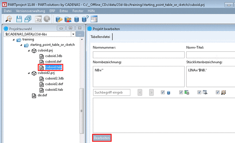
In the project to be edited, select the *.tab or *.tac file.
--> PARTdesigner is opened in the table view.
Alternatively you can open a new characteristic attribute table via File -> New table in the already opened PARTdesigner.
-
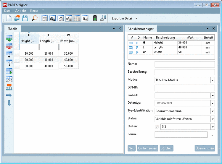
-> The docking window Variable Manager is opened together with the docking window Table by default.
Otherwise you can bring the window to the foreground with the respective menu command or button
 anytime.
![[Note]](/community/externals/manuals/%24%7Bb2b:MANUALPATH/images/note.png)
Note You can place the docking window as desired. On this see Section 3.1.5.4, “Placing method for dockings ” in PARTsolutions / PARTcommunity4Enterprise - User manual.
-
In the Variable Manager, fill out the fields and commit the entries by clicking on .
Note As there exists no 3db file yet, under Mode only the Table mode is displayed.
Detailed information on the single parameters can be found under Section 6.8.3, “ Variable Manager - The individual parameters”.
--> Once after creation of a variable in the Variable Manager, it is also displayed in the table.
-
When wanting to add another characteristic to the table, just click on the button Add row
 .
. -
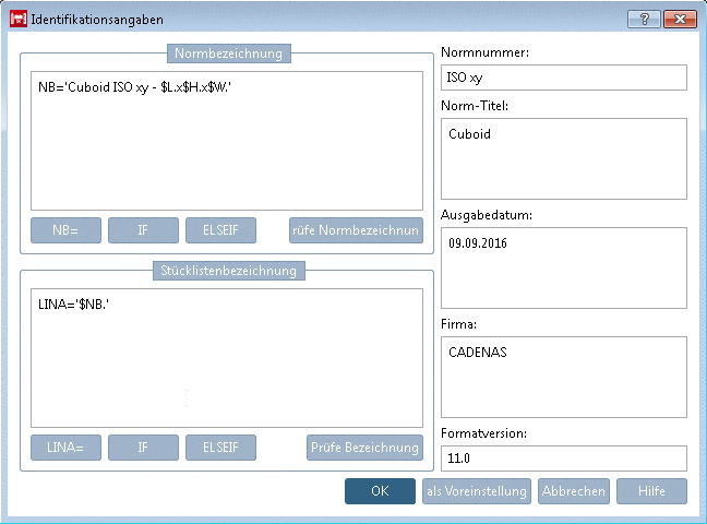
Before saving the table, please enter the necessary ID data. Therefor, in the File menu, click on the command ID data.
-> The same-named dialog box is opened.
-
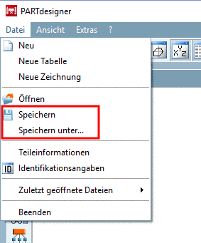
Save the table via File -> Save or Save as into the directory, where the corresponding *.3db and *.prj file is stored.


After finishing the table, in the next step the 3D model is created.
Therefor, open the 3db file from PARTproject. The variables are automatically overtaken from the related (same-named) tab/tac file.
-
Switch all variables to be used in the sketch to Dual mode.[44] Otherwise the error message Unknown variable is displayed.
Information on this can be found under Section 6.8.4.1, “ Unknown variable (Error message) ” und Section 6.8.4, “ Designer mode | Table mode | Dual mode ”.
-
Once the desired variable is saved in the Dual mode, it can be used in sketches.
A small example on the creation of the 3D model can be found under Section 6.4, “Create 3D model: Small example from A to Z ”.


