Manual
Login
Our 3D CAD supplier models have been moved to 3Dfindit.com, the new visual search engine for 3D CAD, CAE & BIM models.
You can log in there with your existing account of this site.
The content remains free of charge.

Top Links
Manual
 |
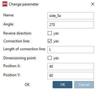
Connection lines can be used for movable elements. For example, for connectors of profiles, which move in a groove.
Connection lines are created from a combination of one "normal" connection point and an absolute plane.
Create connection point (line)
|
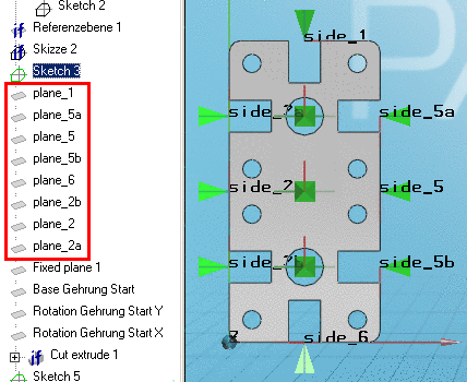
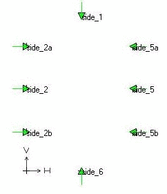
Open a new sketch and enter the desired connection points.
|
|
![[Note]](/community/externals/manuals/%24%7Bb2b:MANUALPATH/images/note.png)
|
Connection lines are identified by pyramid symbol and additionally with a green line at the pyramid's base. |
|
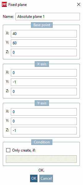
Create absolute plane in connection with connection points
|
Every Connection point needs its Fixed plane. The Base point indicates the starting point of a Connection line.
|
|
![[Important]](/community/externals/manuals/%24%7Bb2b:MANUALPATH/images/important.png)

Name convention plane - connection line
The name of the plane must be plane_<side_nr>.
In other words: The numerical value of a plane corresponds to the numerical value of the respective connection point (connection line):
plane_1 <-> side_1, plane_5a <-> side_5a, etc.
The sum of the numerical values of the opposite connection points must be the same. (In this example: 1+6, 2+5, the sum is 7 both times).