Manual
Login
Our 3D CAD supplier models have been moved to 3Dfindit.com, the new visual search engine for 3D CAD, CAE & BIM models.
You can log in there with your existing account of this site.
The content remains free of charge.

Top Links
Manual
 |
A 3D solid must always be created on a 2D sketch. This 2D sketch is created in its own docking window, the Sketcher.
In the following, with the help of a simple cuboid, the procedure is explained step by step.[75]
-
In PARTproject, create a new project. A small example can be found under Section 5.5, “Create project - Small example from A to Z ”.
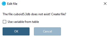
In the project to be edited select the *.3db file.
-> The Edit file dialog box is opened.
-
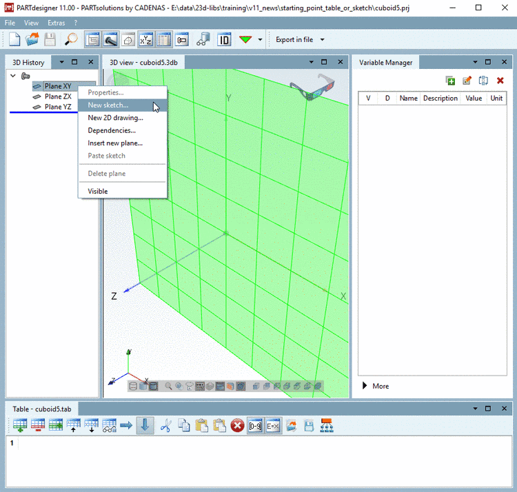
-> PARTdesigner is opened with the docking windows 3D History, 3D view, Variable Manager and Table.
![[Note]](/community/externals/manuals/%24%7Bb2b:MANUALPATH/images/note.png)
Note You can place the docking windows as you wish. On this see Section 3.1.5.4, “Placing method for dockings ” in PARTsolutions / PARTcommunity4Enterprise - User manual.
-
In the 3D History docking window, you can find three basic planes for the design sketches.
With the secondary mouse button, click on one of these planes (in this case XY) and select the menu item New sketch... in the context menu.
-> This command opens the Sketcher.
-
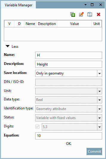
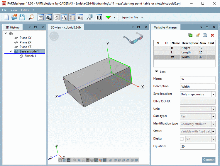
In the Variable Manager, create the variables L (Length), W (Width) and H (Height) for a cuboid. Details on the Variable Manager can be found under Section 7.8, “ Variable Manager docking window ”.
-
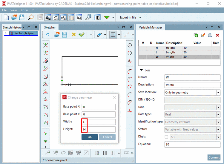
First, draw a rectangle which will be extruded later. Details on the sketcher can be found under Section 7.9, “ Sketcher docking window ”.
Click on the button Insert rectangle
 .
. Set a center point by moving the cursor to the KO origin and simply fix it with a mouse-click.
When moving the mouse cursor, you can draw the rectangle. Fix the size of the rectangle by a simple mouse click.
-
Click on the Accept changes
 button, in order to confirm your entries.
-> In the docking window 3D History the design step Sketch 1 shows up.
-> In the docking window 3D view the rectangle is located on the Plane XY.
-
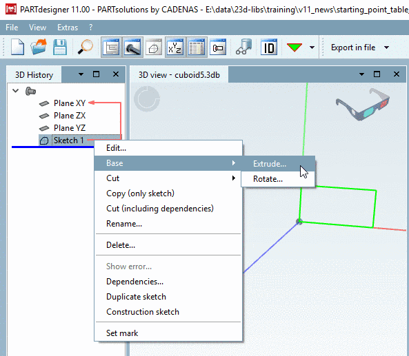
With the secondary mouse button, click on Sketch 1 and choose the command Base, Extrude....
-
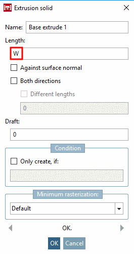
Specify the Length by entering the variable W and confirm by clicking on .
-> Now in the docking window 3D History, in relation with Sketch 1 the design step Base extrude 1 is displayed.
-> In the 3D view the rectangle with the value W is extruded to a cuboid.
-
Finally click on the button Save
 .
.-> The Identification data dialog box is opened with tabbed page Geometry.
-
Fill out the mandatory fields Part name, Author and Catalog key.
Without entering a valid Catalog key remains disabled (grayed out) and you cannot save.
The schema for a valid Catalog key is:[76]
CNS2009*CATALOGS*KATALOGNAME
Here, in the training example in hand, the Catalog key is:
CNS2009*CATALOGS*TRAINING
-
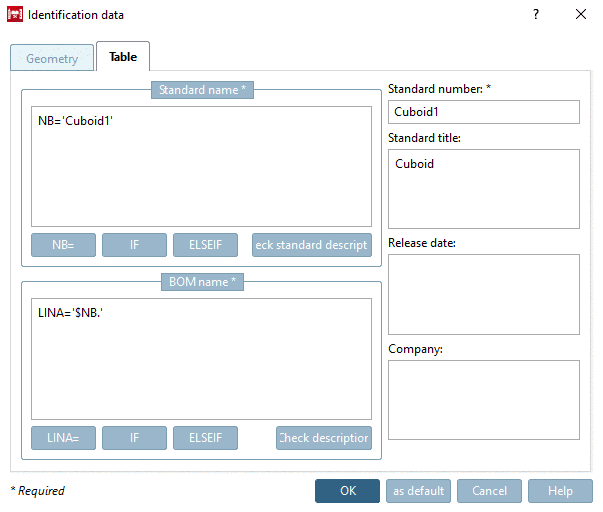
Switch to the tabbed page Table.
Fill out the mandatory fields Standard name, Description for BOM and Standard number. Details on this can be found under Section 7.12.7, “ Identification data ”.
-


|
Note |
|---|---|
|
If a table shall be build, it is necessary to change the parameter Save location in the Variable Manager for all variables from Only in geometry to In geometry and table.
You can recognize the Save location by the respective color: Details on this can be found under Section 7.8.10, “ Save location: Only in geometry | Only in table | In geometry and table ”. Simply select the desired variable, change the list field option and confirm with . | |


Immediately after the change to Save location "In geometry and table" a table with default values is created. This table can be extended anytime.

| ||||
| ||||
