Manual
Login
Our 3D CAD supplier models have been moved to 3Dfindit.com, the new visual search engine for 3D CAD, CAE & BIM models.
You can log in there with your existing account of this site.
The content remains free of charge.

Top Links
Manual
 |
- 7.9.3.10.1.6.1. Function "Generate sketch on selected face" needs at least one edge without Blend
- 7.9.3.10.1.6.2. Several intersecting chamfers/fillets and Blend feature in addition
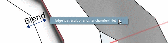
- 7.9.3.10.1.6.3. Edges resulting from Blends
- 7.9.3.10.1.6.4. Maximum radius of Chamfer/Fillet
- 7.9.3.10.1.6.5. Blends whose edges meet with different size each
- 7.9.3.10.1.6.6. Combination of a fillet and a chamfer
- 7.9.3.10.1.6.7. Radius of chamfer/fillet larger than distance to adjoining geometry
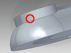
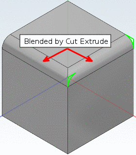
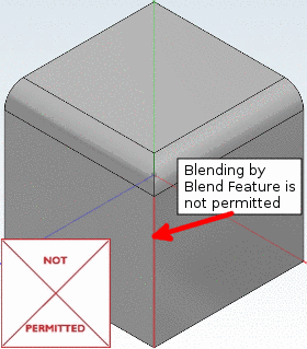
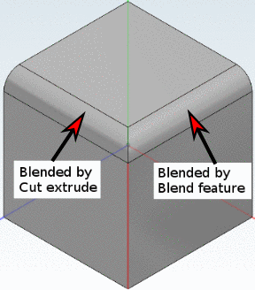
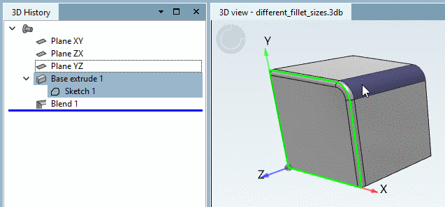
If all adjoining edges of a face have been edited by the Blend feature, the function Generate sketch on selected face cannot be used on this face anymore. This can be recognized by the missing display of coordinate systems.[98]
All 4 edges edited by Blend feature: "Generate sketch on selected face" is not applicable in this situation
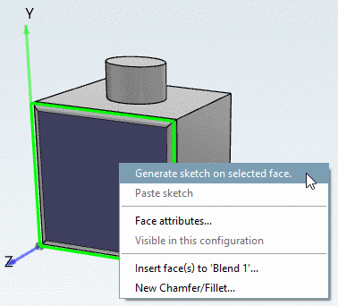
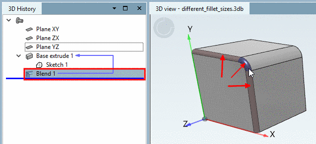
If at least one "free" edge exists, the function Generate sketch on selected face can be used.
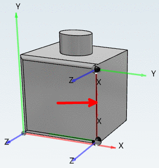
If one edge is edited by sketch and the other 3 by Blend feature, the function Generate sketch on selected face can be used.
If a blend with
radius "a" is to be
applied to a shoulder height "h", the following
applies:
a <= h
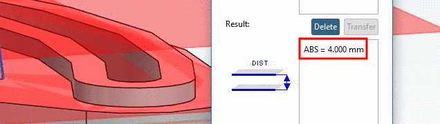
The distance of measured planes (shoulder height "h") is 4 mm here.
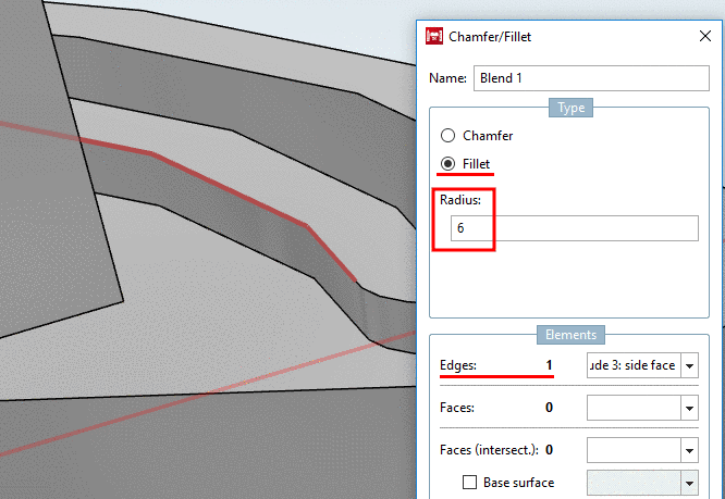

The same applies for chamfers.
If two blends
with radii "a" and
"b" are to be
applied to a shoulder height "h", the following
applies:
a+b <= h


![[Note]](/community/externals/manuals/%24%7Bb2b:MANUALPATH/images/note.png) |
Note |
|---|---|
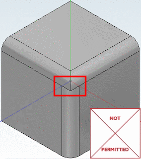
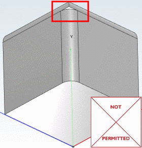
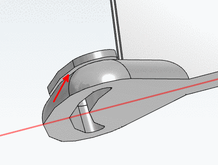
If intersecting edges shall have different sizes, then this cannot be accomplished by the only use of the Blend feature, but only by a combination of Base extrude (sketch) and Blend. | |

-
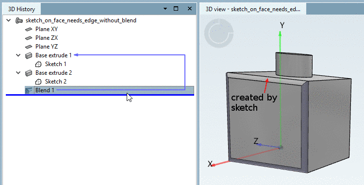
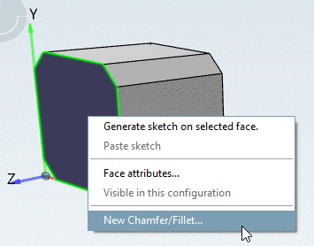
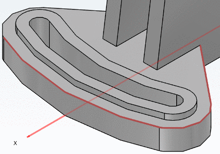
The following figure shows that chamfers have already been created by sketch (green marking).
Now perform a face selection in order for the adjoining edges to be rounded. Then in the context menu, call the command New Chamfer/Fillet....
-
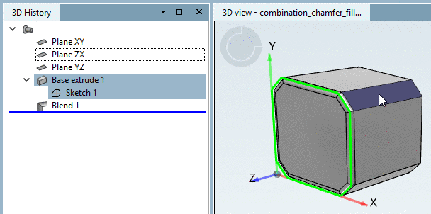
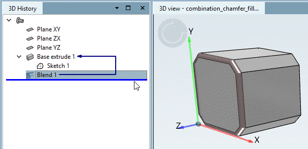
In the 3D History, you can see, which mode had been used for what.
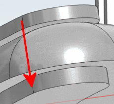
If the radius of chamfer/fillet is larger than the distance to an adjoining geometry, material will be removed from the adjoining geometry. This behavior applies for chamfers and fillets in the same way.
|
Note |
|---|---|
|
Changing the length of extrusion does not affect the behavior, (since the Blend feature has priority and the material is removed anyhow).
| |
The behavior of the CAD systems is different. Material will be added to the extrusion automatically and the shape of the blend will be adopted to the adjacent geometry.