Manual
Login
Our 3D CAD supplier models have been moved to 3Dfindit.com, the new visual search engine for 3D CAD, CAE & BIM models.
You can log in there with your existing account of this site.
The content remains free of charge.

Top Links
Manual
 |
Catalog parts that are going to be used in architectural CAD systems require specific classifications. Via classifications meta-information as well as “relationship-knowledge” will be hosted and transferred to the target systems. Following BIM / AEC classifications do exist today:
| Classification | Author | Purpose |
| ARCHICAD | CADENAS | Placement / geometrical functionalities in ARCHICAD |
| IFC4 | buildingSMART e.V. | Interoperability in the BIM Branch at project- / building level |
| Revit | CADENAS |
Placement / geometrical functionalities in Revit Also see example below. |
| OmniClass 2006 | CSI | Focus: Definition „what“ an object in Revit represents (detailed definition) |
| OmniClass | CSI | OmniClass 2012 is an enhancement of 2006 |
| PDT | CIBSE | Attribution on international level, independent from target system (Excel) |
| UNICLASS | RIBA / NBS | Classification, „what“ product exact it is -> especially UK relevant |
| COBie | buildingSMART e.V. | Construction Operations Building information exchange - Purpose: Bridge between CAD / BIM and facility management |
In the following, an example part will be equipped with the Revit-Family-Templates-Mapping classification:
-
Autodesk Revit uses templates to define the placement of an object within the system.
eCATALOGsolutions modelers can prepare parts that when exporting them to Revit all advantages of these templates with their specific features can be used.
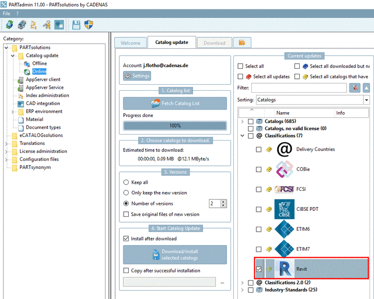
To assign a part / an assembly to a template, the most recent classification "Revit" must be downloaded and installed with PARTadmin.
Start PARTproject and navigate to the part where the classification should be applied.
-
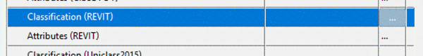
Click on the dots at the end of the line Classification (Revit).
-
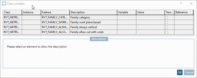
Select the most suitable family template on the right (only one selection allowed) by double clicking. If there is no selection, the system uses the default metric generic model and places the object with the global orientation (X/Y/Z) as it is created in eCATALOGsolutions (no rotation / placement).
In order for the placement feature (suitable for all available templates) really to be able to be used, the geometry must have a published connection point available. The publication is created in the Preview window (as described below).
-
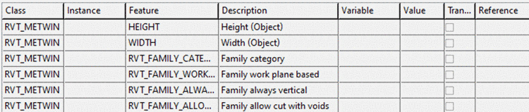
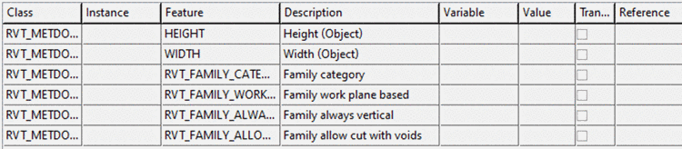
Then click on at the end of line Attributes (Revit).
-
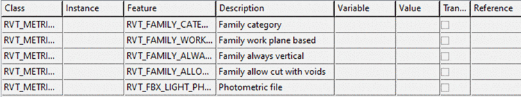
Each template in the Revit classification has its specific features, e.g.
(that can be set by direct values or linked to an eCATALOG table variable)
Special templates have special properties, such as
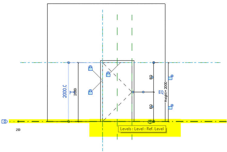
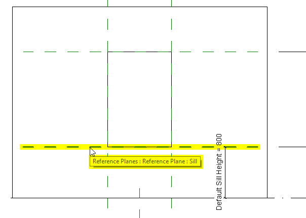
The width and height features (doors and windows) define the raw cut into the wall, from the placement connection point (see below).
Confirm with and switch to the corresponding 3DB file in the PARTproject folder/file structure.
-
The connection point needs to point (orientation of the Z-Axis) into the direction of a Revit reference plane. The exact placement (intersection of 3 reference planes in the Revit Family Template) is defined in the interface configuration. The placement connection point may not be in the "dummy starter part", as it is normally not exported into the CAD (dialog Part properties -> No export), thus not available within the assembly.
Default orientation of placement connection points are as follows:
-
The connection point points to the bottom (Z), the X axis points right and the Y axis to the left.
-
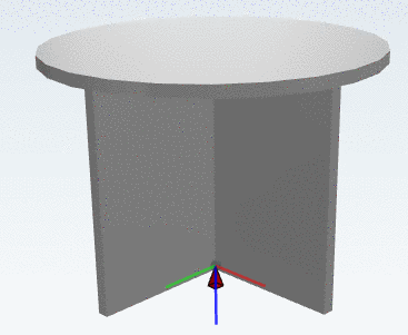
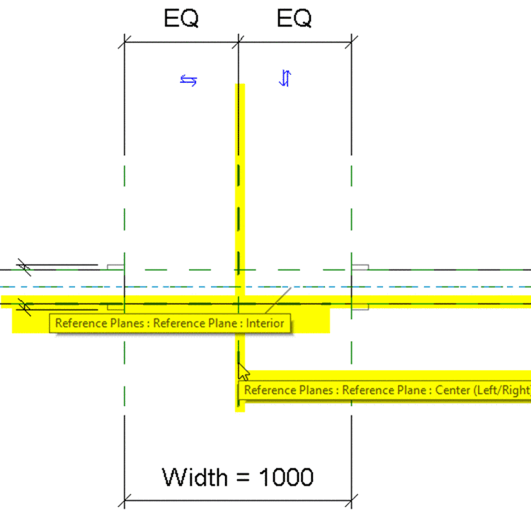
Products that have the class “Metric generic model” assigned, will be placed as follows:
The X axis points towards the “Center(left/right)” plane.
The Y axis points towards the “Center(front/back)” plane.
The Z axis points towards the “Reference plane” (base plane).
-
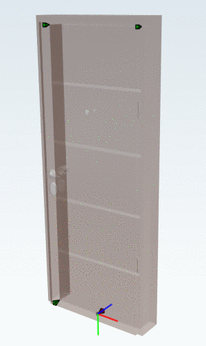
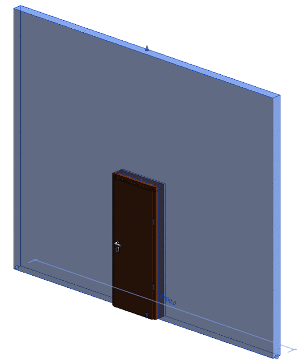
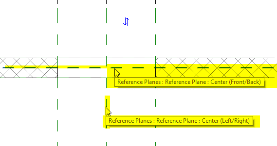
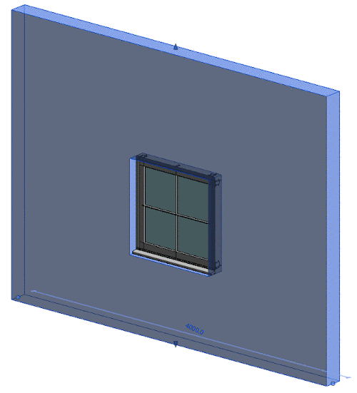
The connection point points to the wall (Z), the Y axis (green) points downwards and the X axis points to the right.
-
The connection point points to the wall (Z), the Y axis (green) points downwards and the X axis points to the right. This is identical with the door template, but the placement of windows is done at the center reference plane of the wall.
-
-
Open the 3DB and place the Connection point required for Revit. The name can freely be chosen, but take care on position and direction.
The Connection point should be in a fixed / static position related to possible variants.
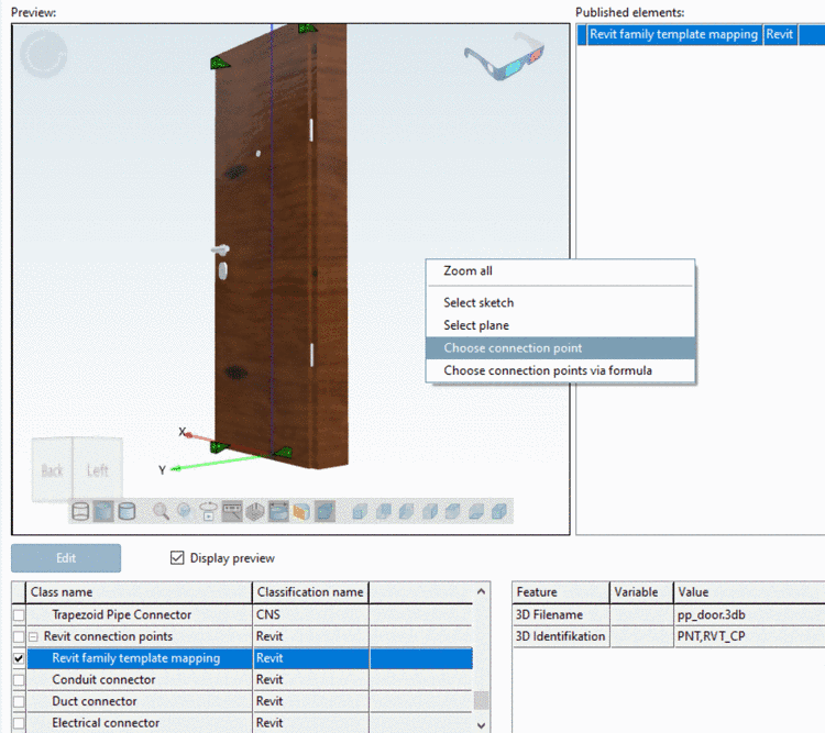
Right click in the PARTproject Preview window and select the command Choose connection point and in the same-named dialog box the desired one.
Then under Class name, please select and activate the Revit family template mapping from the Revit classification.
Additional requirement for assemblies:
If an assembly is used, the connection point to be used has to be made known to it (meaning which part with which connection point).
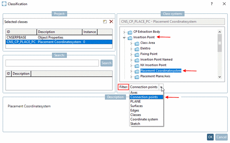
For this, the assembly table project must be classified with the “CNS” classification.
To do that, select the assembly table project, filter for Connection points and then assign the class "Insertion point -> Placement Coordinatesystem".
![[Note]](/community/externals/manuals/%24%7Bb2b:MANUALPATH/images/note.png)
Note The class Placement Coordinatesystem from the CNS classification should not be used anymore until further notice. Compare above.
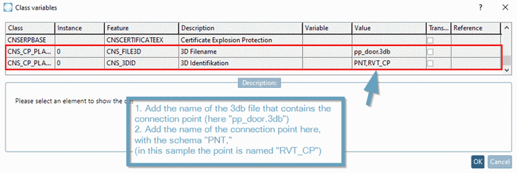
Then publish the name of the 3db file (that contains the connection point) and the name of the connection point with the schema “PNT,%NAME%” (see following figure).
Note The class Placement Coordinatesystem from the CNS classification should not be used anymore until further notice. Compare above.
-
Optionally, you can click again on the PRJ file in the PARTproject folder structure and then check if all entries are set up correctly now in the two classification lines.
-
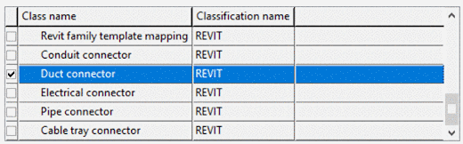
For the case that your geometry has a Connection point for ...
..., which has to be transferred to Revit, please proceed as described above and publish the eCATALOGsolutions Connection point as one of the above mentioned points (the point Revit family template mapping may not be used for this).
Connection points in eCATALOGsolutions can be created anywhere. Functional connectors (suitable for Revit) have to be created at the center of a plane surface (centroid), e.g. the center of a circle or the intersection of all angular diagonals (see https://en.wikipedia.org/wiki/Centroid).
It is recommended to create an extrusion at the position where the connector should be placed. (>1.4 mm diameter / extrusion length).
If it is not possible to have a plane surface in the 3db available, the CADENAS Revit interface will attempt to create a “dummy solid” (2x2x2 millimeter) at the position where the connector should be created. This should not be the preferred way to design a model, as the end result in Revit will not be 100% identical with the eCATALOG model.
The classification is now complete. It is recommended, that a Revit export check is performed additionally in order to check the correct placement and handling of the negative solid.


![[Important]](/community/externals/manuals/%24%7Bb2b:MANUALPATH/images/important.png)


![[Tip]](/community/externals/manuals/%24%7Bb2b:MANUALPATH/images/tip.png)