powered by CADENAS

Manual

Manual

5.10.2.2.  Optional parameters

  • Text

    Default value: {AUTOMATIC}

  • Variable mapping

    No entry per default

  • Font height

    Default value: 3.5

  • Condition

    No entry per default

  • Arrow size

    No entry per default

  • Arrow factor

    No entry per default

  • Arrow position

    • Default: In 3D, arrows and text are inside the dimensioning lines.

    • Keep position: Arrows keep their position in any case, both in 3D and 2D.

    • Flip side: Arrows flip side, text remains centered, both in 3D and 2D.

  • Accuracy

    Default value: 1

  • Force accuracy:

    Enable this option for a consistent depiction of decimal places in the 3D view. Then zeros at the last decimal places are shown.

  • Base dimension

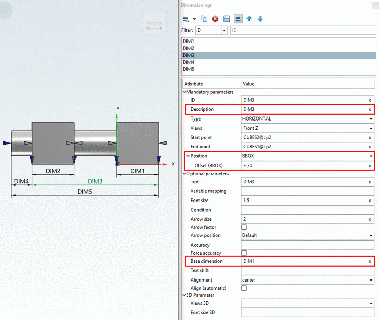
    When entering a dimensioning element's ID under Base dimension, the value stated under Position -> Offset does not refer to the bounding box or the element, but on the stated dimensioning element.

    Elements of the first "offset level" of a chain of dimensions have no entry under Base dimension, but refer to BBOX or ELEMENT.

    1. Under Position either select BBOX or ELEMENT.

    2. Then under Offset (BBOX) or Offset (ELEMENT), enter the desired offset.

    3. Under Base dimension, enter the dimensioning's ID, on which the offset shall refer to.

      It is possible to set the same base dimension for several dimensionings.

    [Note] Note
    • In order to be able to work with the option Base dimension, an ID has to be mandatorily set at all dimensionings used for this. It is entered in the field Base dimension at a subsequent dimensioning. The chain's first dimension has no entry for this.

    • The field ID of a dimension stands for Identifier. Thus the entry here has to be absolutely unique!

    • The Base dimension has to be placed before the dimensioning currently edited in the ID list.

    • Please make sure that all dimensionings can be created.

    • The first measurement in the chain (if defined as BBOX relative) must always be able to be created.

    Have a look on the following example

    For DIM1 and DIM2 there is no base dimension. They have the same distance to the bounding box, because under position, the same settings are made.

    DIM3 and DIM4 have both "DIM1" as base dimension, so for these two the offset does not refer to the bounding box, but the value set under Position -> Offset is added to the offset of "DIM1". Just as well "DIM2" could have been set with the same effect.

    DIM5 has DIM3 as base dimension. So the set offset also here, does not refer to the bounding box, but is added to the offset of DIM3.

    Here in this example you can see that the offset "DIM3" refers to the base dimension "DIM1".

    Here in this example you can see that the offset "DIM3" refers to the base dimension "DIM1".

  • Text shift (on the dimensioning arrow)

    [Note] Note

    The option is only available at the dimensioning type HORIZONTAL.

    The value determines the horizontal text shift from center.

  • Alignment

    [Note] Note

    The option is only available at the dimensioning types HORIZONTAL, VERTICAL and PARALLEL.

    Align dimensioning arrows / position dimensioning text

    Example

    Example

    In the list field, select one of the following values:

    • left

      The arrowheads show on the dimensioning lines from outside.

      The dimensioning text is located on the left dimensioning arrow.

    • center

      The arrowheads show on the dimensioning lines from inside.

      The text is centered on the arrow.

    • right

      The arrowheads show on the dimensioning lines from outside.

      The dimensioning text is located on the right dimensioning arrow.

    Align (automatic)

    • Checkbox deactivated: Alignment is considered in any case

    • Checkbox activated: Alignment is only considered, if the dimension does not fit between the arrows.

You can find detailed information under Section 5.10.7, “ Optional parameters Details ”.