Manual
Login
Our 3D CAD supplier models have been moved to 3Dfindit.com, the new visual search engine for 3D CAD, CAE & BIM models.
You can log in there with your existing account of this site.
The content remains free of charge.

Top Links
Manual
 |
![[Note]](/community/externals/manuals/%24%7Bb2b:MANUALPATH/images/note.png)
Each dimensioning must contain the following parameters:
-
ID is only required, if a dimensioning serves as Base dimension for another dimensioning. Also see Section 5.10.2.2, “ Optional parameters ” -> Base dimension.
-
The description is automatically set and displayed in listing of dimensionings. You can adjust it as desired.
-
When creating a new dimensioning, initially HORIZONTAL is automatically set. Adjust the selection in the list field, if needed. You can change the type anytime.
Under "Type" the following options are selectable:
-
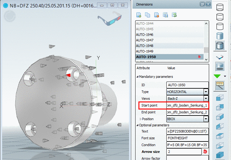
At the desired 2D views, where the dimensioning shall be displayed, activate the checkbox.
Views which contain a dimensioning, can be recognized in the 3D toolbar, by a respective icon with dimensioning lines
 .
. -
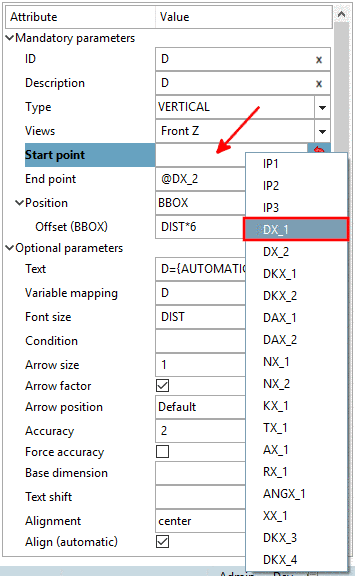
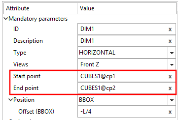
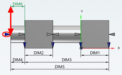
In order to select start and end point you have different options available:
-
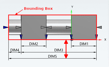
You can refer to the Bounding Box or the element or use absolute values:
-
BBOX: Distance to bounding box.
-
ELEMENT Distance to the element itself to be dimensioned. Reference point is the connection point.
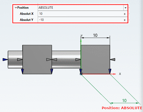
-
ABSOLUTE: Distance to the element itself to be dimensioned. Reference point is the element's origin. The specification happens via X and Y coordinate. In this way angular dimensionings can be set.
Offset: The value can be fixed, build by a variable or by PARTdesigner-Expressions (see Section 15.1, “PARTdesigner-Expressions ”).
Example PARTdesigner-Expression:
15*RZ500@D/20
-