Manual
Login
Our 3D CAD supplier models have been moved to 3Dfindit.com, the new visual search engine for 3D CAD, CAE & BIM models.
You can log in there with your existing account of this site.
The content remains free of charge.

Top Links
Manual
 |
In order to insert parts into a configuration, on the Parts item, call the context menu command Add Part.

-> An Explorer window is opened.

Select a Project file (*.prj) and confirm by clicking on .
-> The dialog box Part properties is opened.

File name: ...is automatically entered. Storage location of part.
Description: ...for the part within the configurator directory.
-
Equation name: ...for internal referencing of the part. Located in parenthesis behind description.
-
Start element: The part, from which the creation of a system of rules is to begin, is defined as the Start element. Set a checkmark at the respective option. Start elements are identified by a red circle
 in the directory tree.
![[Note]](/community/externals/manuals/%24%7Bb2b:MANUALPATH/images/note.png)
Note You may also define more parts as start elements!
Important! See also Section 9.8, “Example 2 - Create an Assembly Table Project ”.
Multiple usage: A part can be inserted in different positions and with different dimensions into the assembly.
-
This option enables a vector shifting to any place in space.
As soon as the option has been activated, the button becomes active.
When clicking on , the dialog box Fixed positioning is opened.
The dialog is divided into 3 sections.
In above example, the part was moved 5 units to the right on the x-axis and at level x-y (z=0) with vector (1; 0,1) moved upwards. In respect to the orientation to the y-axis, no changes were made.
Hide table: The according table is no longer visible in the PARTdataManager.
-
No export: During export of the table from PARTdataManager to a CAD system this part is not exported.
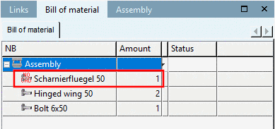
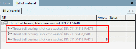
Parts with the No export option will get the NO CAD
 icon in PARTdataManager, in the dialog area
Assembly, Bill of material (see following
figure). [105]
icon in PARTdataManager, in the dialog area
Assembly, Bill of material (see following
figure). [105]
-
Transfer to Bill of Material: The respective part is taken over by PARTbom order list.
Parts without the option "Transfer to Bill of Material" show up grayed in the PARTdataManager, in the dialog area Assembly, Bill of material (see following image: "NO BOM"). [106]
-
Cut in 2D: ... defines whether the part in the cut should be affected in 2D as well. Remove the checkmark for screws, for example, that you do not want to be displayed shaded during cutting.


[105] On this, also compare Fenster "Aufbau" - Stückliste.
[106] Compare also Section 3.1.11.15, “"Assembly" Window - Bill of material Window ” in PARTsolutions / PARTcommunity4Enterprise - User manual.
