Manual
Login
Our 3D CAD supplier models have been moved to 3Dfindit.com, the new visual search engine for 3D CAD, CAE & BIM models.
You can log in there with your existing account of this site.
The content remains free of charge.

Top Links
Manual
 |
Drawings can be enhanced with BMG layers according to DIN 4003. When exporting 2D DXF/DWG these layers transfer important information for Tooling and BIM, among others.
Precondition: CNS classification with respective data
-
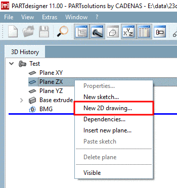
In PARTdesigner, in the docking window 3D History, click on the context menu command New 2D drawing....
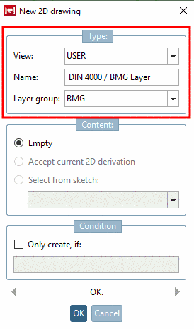
-> The dialog box 2D drawing is opened.
-
Under View, select the option User.
Under Name, for example enter DIN 4000 / BMG Layer.
Under Layer group, select the option BMG.
-> The Sketcher is opened. (The button group Text
 is visible for drawings.)
 -
In the Sketcher, create your drawing as usual.
-
Now classify desired elements.
-
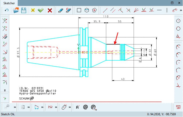
Initial situation: A line not yet classified shall be classified.
-
-> Now the line is displayed showing the default highlighting color (purple).
-
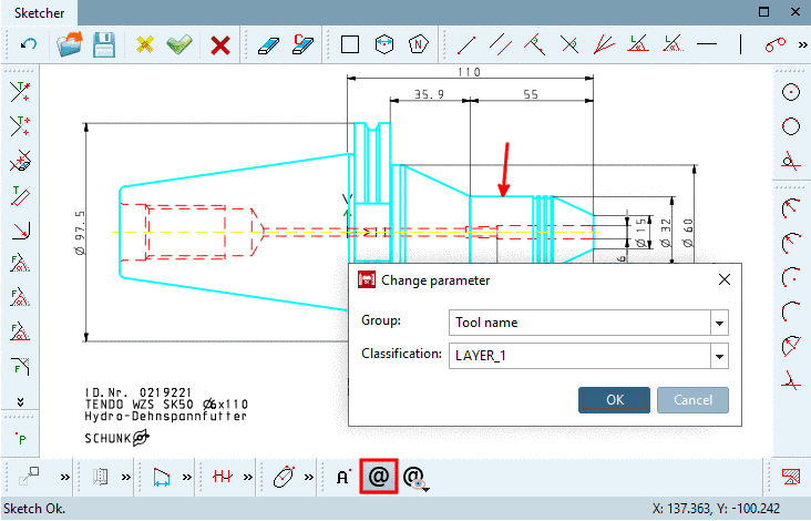
Click on the icon Classify element
 .
.
-> The respective dialog box for specification of Group and Classification is opened. Select desired options (here Tool name and LAYER_1.
Once selecting a layer, the result to be expected is immediately displayed (line color, type, width).
-
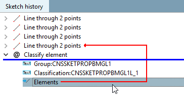
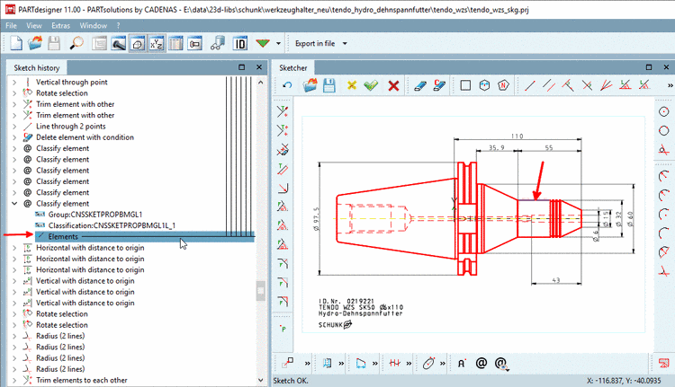
Confirm your selection by clicking .
-> In the Sketch history, the relation between shape element and classification is represented by a red arrow.
-
-
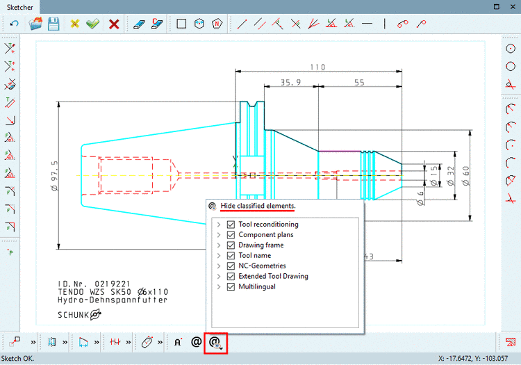
With Hide classified elements
 , you can hide or show all layers of a group or
single layer and check in this way, if everything has been set
correctly.
, you can hide or show all layers of a group or
single layer and check in this way, if everything has been set
correctly.
-> The respective dialog area is opened.
Activate/deactivate the checkbox at desired groups or layers.
-
In the Sketcher, finally click Accept changes.
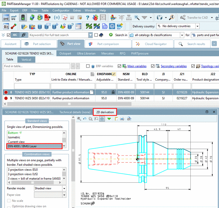
-> The additional drawing with the layer information is displayed in the 3D History.
-
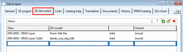
Under PARTproject -> Edit project -> tabbed page 2D derivation, determine that the 2D sketch is displayed.
-
-> The additional drawing is displayed under 2D derivation.
![[Note]](/community/externals/manuals/%24%7Bb2b:MANUALPATH/images/note.png)