Manual
Login
Our 3D CAD supplier models have been moved to 3Dfindit.com, the new visual search engine for 3D CAD, CAE & BIM models.
You can log in there with your existing account of this site.
The content remains free of charge.

Top Links
Manual
 |
Published elements are used for standard parts in order that parts exported from PARTsolutions can easier be placed in the CAD system. When parts with published elements are used then automatically the PARTsolutions placement dialog shows up in the CAD system.
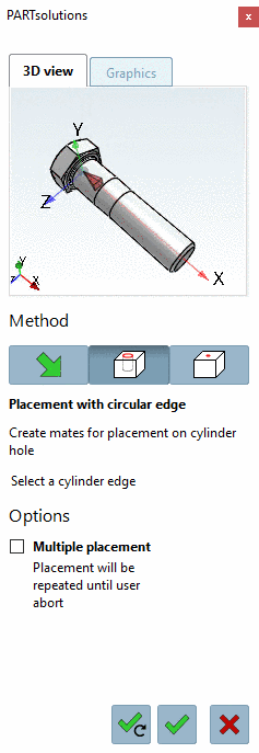
In order for a fastener e.g. to be placed in a hole it needs a defined orientation in the coordinate system.
Therefor the already existing connection points are used, because these already have a complete coordinate system.
A plane and an axis (with direction) have to be defined.
The Z axis of the connection point determines the axis, X and Y axes determine the plane.
The realization happens with Published elements. Therefore the current CNS class system must be installed.
For setting published elements proceed as follows:
-
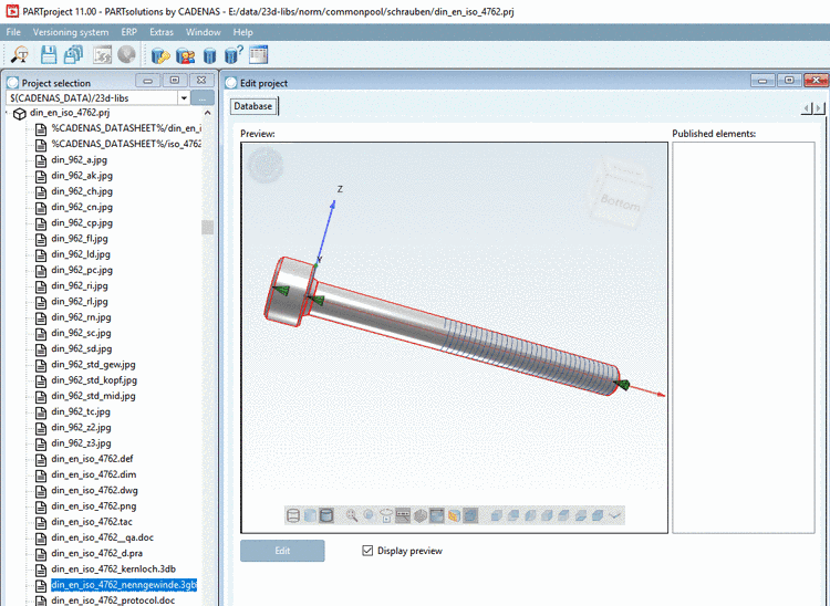
In PARTproject, select the 3db file of the part.
-
For setting the published elements use the preview area in PARTproject, which displays if you have selected a 3db file under Project selection on the left.
-
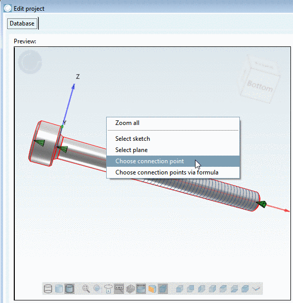
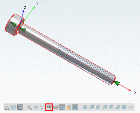
Right-click in the 3D area and select Choose connection point in the context menu.
-
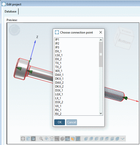
Choose the desired connection point and confirm with .
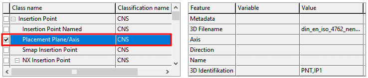
-> The dialog area for selection of Class name and Feature is opened.
-
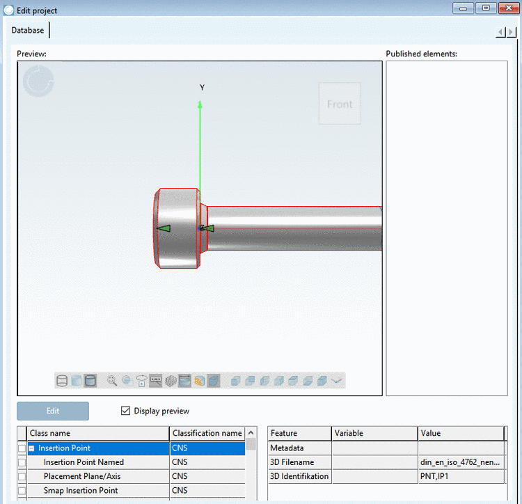
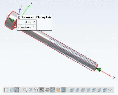
Activate the checkbox at Placing plane/axis.
-
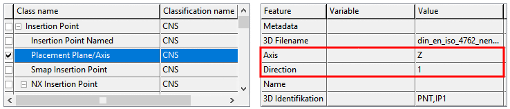
In order to clearly orient the published element set the following 2 parameters:
-
Axis identifies the axis of the connection point to be used for the positioning. If the green pyramid points vertically to the bearing face it is the Z axis.
-
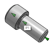
There are two values possible:
1: The part is inserted in positive direction of the Z axis (e.g. in bolts).
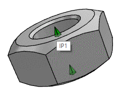
0: The part is inserted in negative direction of the Z axis (e.g. in nuts).
-
-
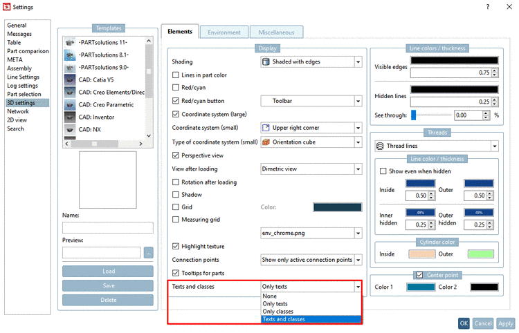
Determine if Published elements shall be shown in PARTdataManager.
Under PARTdataManager -> Extras -> Preferences -> 3D settings -> Elements -> Display -> Texts and classes perform the desired default setting.
Via toolbar button Show texts and classes you can switch on and off the display anytime.
![[Note]](/community/externals/manuals/%24%7Bb2b:MANUALPATH/images/note.png)