Manual
Login
Our 3D CAD supplier models have been moved to 3Dfindit.com, the new visual search engine for 3D CAD, CAE & BIM models.
You can log in there with your existing account of this site.
The content remains free of charge.

Top Links
Manual
 |
- 5.10.1. Example: Create dimensioning
- 5.10.2. Horizontal, vertical and parallel dimensioning
- 5.10.3. Radial dimensioning
- 5.10.4. Angular dimensioning
- 5.10.5. Annotation
- 5.10.6. PART-ANNOTATION
- 5.10.7. Optional parameters Details
- 5.10.8. 3D Parameter
- 5.10.9. Using variables
- 5.10.10. PARTdesigner Expressions
For Part selection in PARTdataManager, dimensionings are automatically created in 3D view and 2D derivation. When exporting the part, the 2D derivation is transferred to the CAD system.
During modelling process respective data is parametrically created in PARTdataManager in the dialog area Dimensionings. Certain dimensions can be set editable so that end users can click them in the 3D view and in this way select alternative characteristics (see Section 5.10.7, “ Optional parameters Details ” -> Variable mapping).

| Horizontal, vertical and parallel dimensioning | Radial dimensioning | Angular dimensioning | Annotations / Position numbers for list of material |
|
|
|
|
|
|
|
|
|
|


-
If the docking window Dimensionings is not displayed, call it via context menu command in the toolbar or menu. Activate the option.
Make sure that the connection points are shown in the 3D view.
For this, in the Assembly toolbar, click on the button Show connection points, if needed.
If not displayed, in addition, click on the button Show configurations and tables
 .
. -
At first set needed dimensioning points - if not available yet
Since the measuring points reference to dimensioning points/connection points, they must either already be available within the part or specifically set.
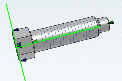
The Connection points (in parts, displayed in green, in assemblies, in gray) can also be used like Dimensioning points (displayed in blue).
Absolutely, please regard on which face/plane the Dimensioning points are set!
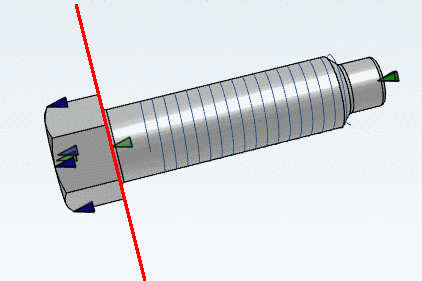
If dimensioning points are not set correctly, dimensionings are shown like they were pointing to a wrong place in the 3D view, when setting option Perspective projection is selected.
The dimensioning points should be moved to the nearest position in direction of viewer.
-
File for saving the dimensioning parameters
If there is no file for saving the dimensioning parameters available yet, in the project, a file same-named to the project
*.dimis automatically created and the key CUSTOMDIMENSIONSV9 in the Assembly Configuration project file (*asmcfg.prj), Assembly Template project file (*asmsbl.prj) or Single Part project file (*.prj) points to this*.dim.If a file
customdimensions.txtstill exists from earlier versions, it will be used further on and data is read and saved from there.


Do not use translations for automatic dimensioning! [46]Use instead a Value range variable with naming with neutral text.
-
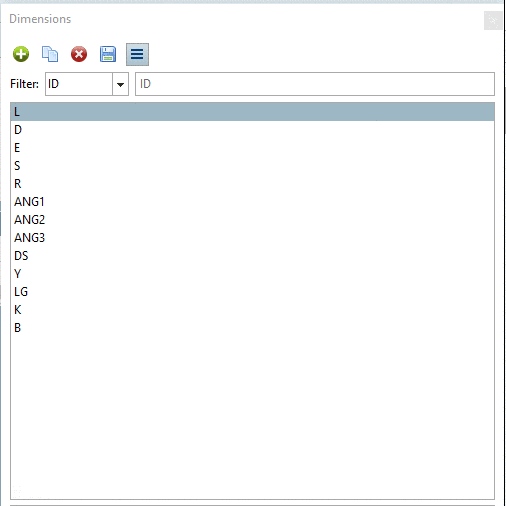
Working area is the docking window Dimensionings. It is subdivided in two dialog areas:
In the upper dialog area, all dimensionings are listed with their description (ideally identical to the variable name such as L, R, D, etc.), in the lower area, the particular parameters of the selected dimensioning.
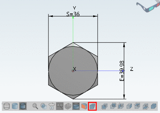
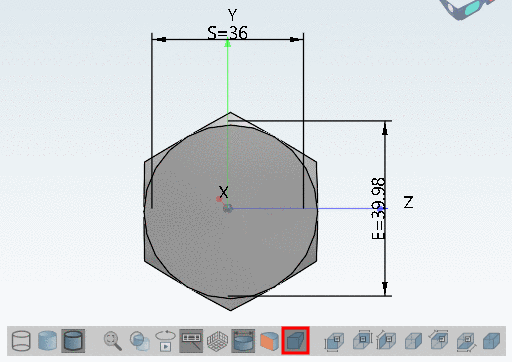
When selecting a dimensioning, the respective view in the 3D view is marked in green, Start point and End point in red. Vice versa, when selecting a dimensioning in the 3D view, the respective line is marked on the right side.
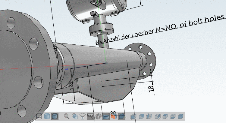
As soon as all Mandatory parameters are set, the dimensioning is displayed in the 3D view.
As soon as all Mandatory parameters are set, the dimensioning is also displayed in the 2D derivation.
-
When selecting a dimensioning line, in the lower dialog area, all parameters of this dimensioning are listed, namely separated in Mandatory parameters, Optional parameters and 3D Parameter. Here, parameters can be set or changed. Changes become immediately visible in the 3D view (if the mandatory parameters are set).
You can find detailed information on the mandatory parameters in the single chapters of the dimensioning types. Detailed information on the optional parameters can be found in an own chapter Section 5.10.7, “ Optional parameters Details ”.
-
Value changes are signalized, once at the parameter itself by an undo icon
 (when clicking on the icon the change is
reversed) and once in the list of dimensionings by red bold
font.
(when clicking on the icon the change is
reversed) and once in the list of dimensionings by red bold
font.The undo icon is displayed, as long as the change has not yet been saved by clicking on Save changes
 . After this undo is not possible anymore.
 -
Above the listing of dimensionings the following buttons are shown:
-
-> A new dimensioning is added to the list. At first the Type HORIZONTAL is displayed. If needed, adjust the selection in the list field under "Type". You can adjust the Type anytime.
-
–> A copy of the dimensioning selected in the list is created.
-
–> The selected dimensioning is removed from the list. However, not until Save changes
has been clicked, the deletion is complete
and there is no "Undo" anymore. -
–> Changes are saved in the file
*.dim.As long as you do not click on the button Save changes
, at the ID line above and at each changed
parameter an icon is displayed. Clicking on the icon you can
undo the respective action. -
All gray (inactive) lines are hidden. Compare Section 5.10, “Specify automatically created dimensionings (notations) for 3D view and 2D derivation ”.
-