-
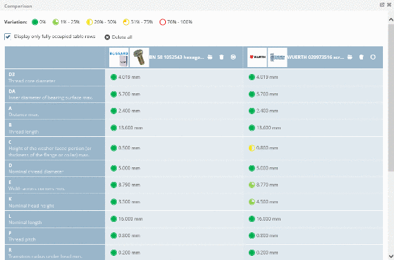
Use the filter, especially for parts with many rows (characteristics), in order to minimize the number of displayed rows.
Follow the steps listed below to filter for certain variables:
-
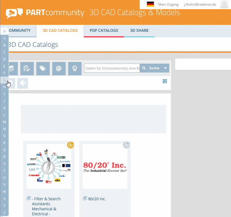
Make sure that your are in the dialog area 3D CAD CATALOGS and search for the required part.
-
At directory level
 select product groups as long as a concrete assembly
  or concrete single part
  has been specified and choose an assembly or a single part.
-
For tables with many values (columns) switch into Full screen mode by clicking on the icon
 .
.
-
Click on the filter symbol
 in the column header of the respective variable with which you want to filter.
-
Make your preferred settings. Then click on Apply to confirm your entries.
-> If you want to change your entries click on Reset. If you want to return without changes click on x.
-> Only CAD models are shown which correspond to the filter settings.
-
In order to delete the filter settings, click on Remove all filters.
0 comments, 0 likes, 8,061 views100% users marked this FAQ as helpful. -
-
*.partcommunity.com
*.partserver.de
to your list of trusted websites:
eg.
Internet Explorer -> Tools -> Internet Options -> Security -> Trusted Sites
Alternatively you can also try to use a different browser.
Contact your local IT for help changing settings if necessary!
If the proposals do not work please contact the support of the partner portal directly, because sometimes Free mail addresses like abc@gmx.de are blocked by our partner portals.
X
1 comment, 0 likes, 9,571 views -
Follow the steps listed below to send a CAD model to your e-mail address.
-
Make sure that you are in the dialog area 3D CAD CATALOGS and navigate to the required part.
-
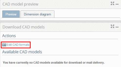
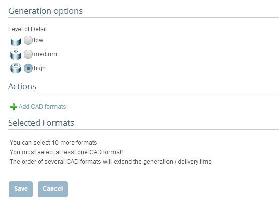
In the dialog area Download CAD models under Edit CAD formats -> Add CAD formats, select the transfer mode email by clicking into the option field. Then define one or more CAD formats and confirm your entries by clicking on Save.
-> The view returns to the dialog area Generation options / Selected formats. Confirm your entries by clicking on Save.
-
Under Actions, click on Generate CAD MODEL.
Note
All formats selected under Download CAD models (dialog area 3D CAD CATALOGS) -> Edit CAD formats ->Selected Formats are generated.
As long as the generation is running, is shown.
 -
As soon as the generation has completed, you will get informed by the note Check your emails that the component was sent by e-mail.
If you close this window, further CAD models can be selected.
Furthermore all generated CAD models are listed under Download CAD models.
-
After clicking on the link Info specific part information is displayed:
-
Status information about generation
-
All formats activated under Download CAD models (dialog area 3D CAD CATALOGS) -> Edit CAD formats -> Selected formats are generated and listed here now.
For some formats you can get some CAD specific information by clicking the Info-Icon
 .
.
The same Info icon you can find underDownload CAD models -> Actions.
In order to import models into the CAD system, do the following:
0 comments, 0 likes, 9,282 views50% users marked this FAQ as helpful. -
-
Follow the steps listed below to integrate the chosen CAD model into your CAD system directly:
-
Make sure that you are in the dialog area 3D CAD CATALOGS and navigate to the required part.
-
In the dialog area Download CAD models under Edit CAD formats -> Add CAD formats, select the transfer mode directIntoCad by clicking into the option field. Then define the CAD system and confirm your entries by clicking on Save.
-> The view returns to the dialog area Generation options / Selected formats. Confirm your entries by clicking on Save.
-
Under Actions, click on Generate CAD model.
-> The information dialog Generating CAD models opens.
Note
All formats activated under Download CAD models(dialog area 3D CAD CATALOGS) -> Edit CAD formats -> Selected Formats are generated and listed here now.
As long as the generation is running, is shown.
-
As soon as the generation has completed, you can submit the CAD models to the CAD system in this window directly by clicking the link Direct integration.
If you close this window, further CAD models can be selected.
Furthermore all generated CAD models are listed under Download CAD models.
-> In the transfer mode Direct integration into CAD system the link text in the column Actions will be the following:
-
By clicking the link Info specific part information is displayed:
-
Click on the link Direct integration or the symbol
 , in order to load parts into the CAD system.
Note
The application component PART2cad is required at the workstation when using direct integration.
Install it during the first run. The necessary installer opens automatically.
The installer itself needs Java.
-> Once Java is installed the PART2cad installation will start. If Java is not installed, there will be no Java logo displayed. In this case click on the link Click here and install Java.
-> Warning messages may show up. Let the component PART2cad install.
During the first run the direct integration PART2cad will be downloaded.
Following runs will open the dialog Transferring model to CAD. No user interaction is necessary.
-
In the drop-down menu select the CAD version where the model is to be transferred. Confirm the selection with Choose.
-> A dialog box "Export ..." is opened to select the destination directory.
-
Select the preferred destination directory. Use ... to browse. Confirm your entries by clicking Ok.
-> The model is transferred to the CAD system.

Note
When the transfer to the CAD system is finished a message will be shown.Please note the following selection dialog for the version name of the CAD system.
-> The part has been imported in the CAD system.
If the CAD system is not started or the wrong version was chosen, an error message will be shown.
0 comments, 0 likes, 8,130 views -
-
Follow the steps listed below to download a CAD model:
-
Make sure that you are in the dialog area 3D CAD CATALOGS and navigate to the required part.
-
In the dialog area Download CAD models under Edit CAD formats -> Add CAD formats, select the transfer mode download by clicking into the option field. Then define one or more CAD formats and confirm your entries by clicking on Save.
-> The view returns to the dialog area Generation options / Selected formats. Confirm your entries by clicking on Save.
-
Under Actions click on Generate CAD model.
Note
All formats selected under Download CAD models (dialog area 3D CAD CATALOGS)
-> Edit CAD formats -> Selected Formats are generated. As long as the generation is runningis shown.
-
As soon as the generation has completed, the CAD models can be downloaded in this window directly. For this click on Download.
If you close this window, further CAD models can be selected.
Furthermore all generated CAD models are listed under Download CAD models.
-> At the transfer mode CAD models to download, in the column Actions, the link text will be the following:
-
After clicking on the link Info specific part information is displayed:
In order to import the models into the CAD system, do the following:
0 comments, 0 likes, 9,205 views0% users marked this FAQ as helpful. -
-
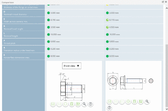
As soon as a CAD model has been selected, in the dialog area CAD model preview the
Dimension diagram tabbed page shows the 2D views.
Note
Always a default dimension view is displayed (created for a middle row) and this may differ from your selected part.
-
Under Actions click on Dimension diagram to get 2D views of the chosen part.
-
By clicking on a Preview you can select the desired dimensioning view.
-
In the toolbar, move the mouse pointer over the icons in order to receive information about the icons.
0 comments, 0 likes, 9,525 views -
-
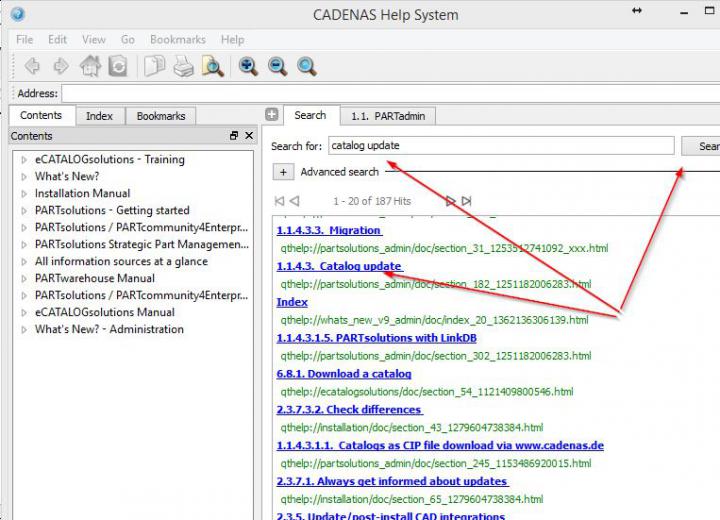
open module PARTadmin -> ...-> Online
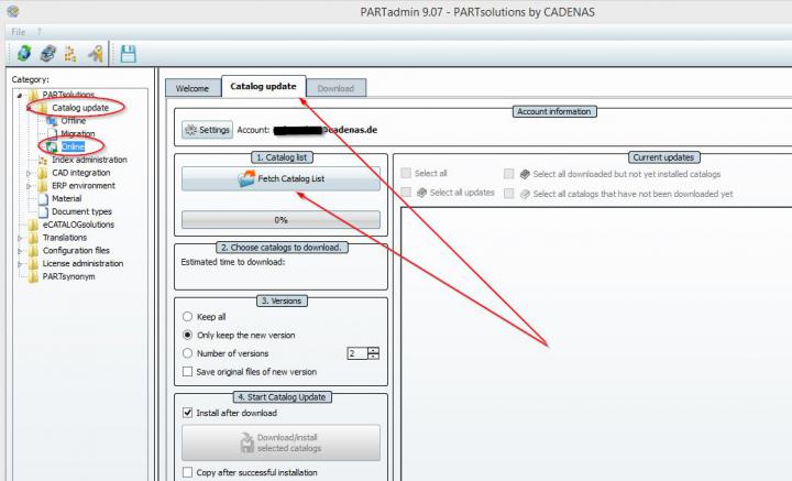
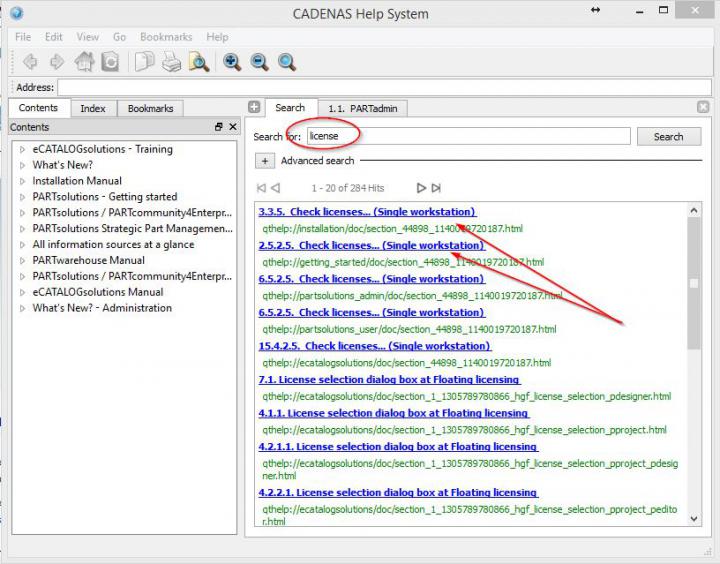
further help regarding updating catalogs by clicking F1 within PARTsolutions
 0 comments, 0 likes, 14,289 views100% users marked this FAQ as helpful.
 -
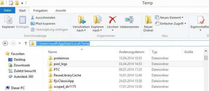
1.
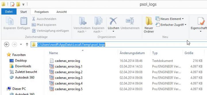
Please delete from folder %temp%/psol_logs (within WINexplorer) al files.
Now please reproduce the problem and send logfile from this folder.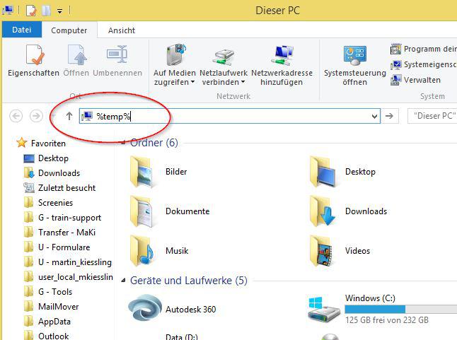
2.
Click button F7 while PARTdatamanager is opend and send the file systeminfo, too.
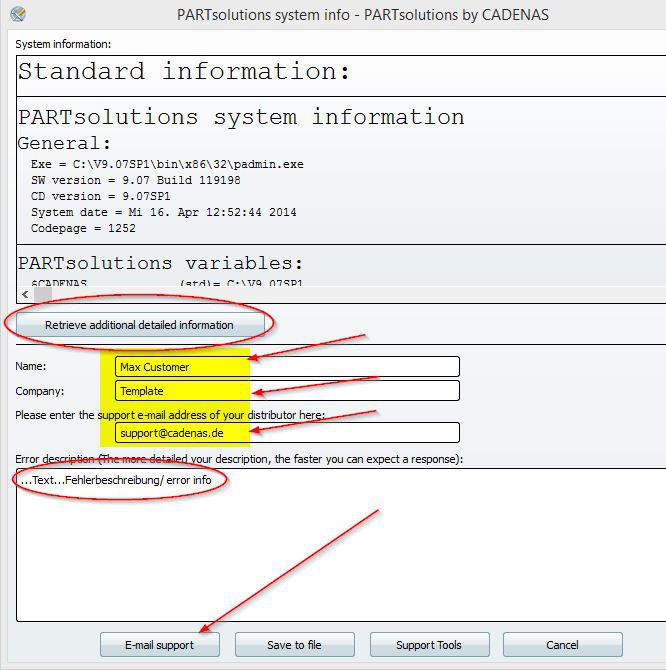
3. (only if problem with a special part)
Please open the part in PARTdatamanager an export it as PS3 V2 3D and add this file, too.
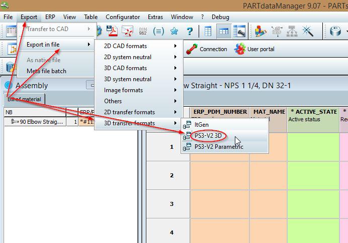
Please send data to support@cadenas.de
0 comments, 0 likes, 15,366 views50% users marked this FAQ as helpful. -
1. Please use the form which can download with the following link:
Hardware exchange
2. For licensing the Host-ID (MAC address) of the old and the new computer is required.
-> The Host-ID can be selected in the license manager PARTadmin.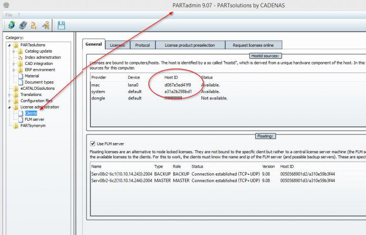
3. Get further help regarding licensing by clicking F1 within PARTsolutions
 0 comments, 0 likes, 15,647 views100% users marked this FAQ as helpful.
 -
Follow the steps listed below to carry out the geometric similarity search:
-
Make sure that you are in the dialog area 3D CAD CATALOGS and search for the required part.
-
At directory level
 select product groups as long as a concrete assembly
  or concrete single part
  has been specified. Select the desired part by clicking into the option button before the desired row.
-
Click on Geometrical Search.

-> The similar parts found are listed in the dialog area Results.
0 comments, 0 likes, 9,009 views -
-
Some parts contain value range fields. In order to completely specify the part, a selection must be made in the value range fields.
The settings are made in the Variables section.
Follow the steps listed below to set the value ranges:
-
Make sure that you are in the dialog area 3D CAD CATALOGS and search for the required part.
-
At directory level
select product groups as long as a concrete assembly or concrete single part has been specified. Select the desired part by clicking into the option button before the desired row. -
Click on the part description in order to reach the variable view.

-> You will recognize the value range fields based on their yellow background color.
There are different types of value range fields:- List fields
Using the arrow open the value range field and select the desired value.

Then select the desired value.

- Input fields or selection via slider
Enter the desired value manually or set it using the slider in the given area.
Note
Inputs outside of the allowed value range are automatically corrected.
- Value range fields with images
Some catalogs support images for variant selection.
Click on the image in order to set another value.
-> A dialog opens for choosing the characteristic per image.
Select the desired variant by clicking on the image.
-> It is reloaded into the variable view.
If you do not want to take over the changes, click on x.
The part is now completely specified.
0 comments, 0 likes, 7,658 views -
-
Follow the steps listed below to define the characteristic of the part:
-
Make sure that you are in the dialog area 3D CAD CATALOGS and search for the required part.
-
At directory level
select product groups as long as a concrete assembly or concrete single part has been specified and choose an assembly or a single part.
-
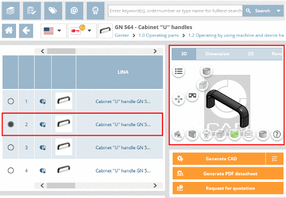
Define the characteristic of the part, by clicking into the option field of the desired row.
-> A default view of the selected model which may differ from the selected characteristic, is displayed under CAD model preview.
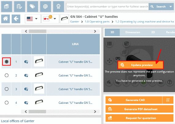
Note
If you want to view an exact replication of the characteristic, under Actions click on Generate preview.
-
Switch to the variable view by clicking on the part description.
-
The variable view shows all important data of a specific characteristic in a compact form.
0 comments, 0 likes, 9,465 views -
-
Follow the steps listed below to generate a PDF datasheet:
- Make sure that you are in the dialog area 3D CAD CATALOGS and select the desired catalog.
- At directory level
 select product groups as long as a concrete assembly
 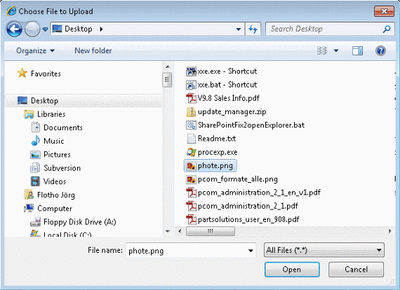 or concrete single part
  has been specified.
-> As soon as a concrete row has been determined, a 3D view and dimensional drawings are loaded under CAD model preview.
- Under Actions, click on Generate PDF datasheet.
- The information dialog Generation CAD models opens.
Note
If the CAD model shall be generated in several formats under Format selection there is the possibility to choose the format PDF Datasheet additionally. By holding down the CTRL key, you can make multiple selections.

- Under Actions, click on Generate CAD model.
- The information dialog Generating CAD models opens.
-> The generation was started.
The following symbols show the generation status: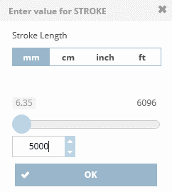 Active generation
 Generation erroneous
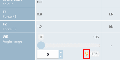 Generation successfull. Part ready for download.
Note
The pregenerated 3D PDF corresponds to a sample part (created for a mid-row with standard setting) and may differ from your selected part.
0 comments, 0 likes, 9,140 views